LoRa with the ESP32 and Semtech SX1262
In my article on the theoretical foundations of LoRa, I explained how CSS modulation works and the importance of parameters like spreading factor and bandwidth, which give LoRa its extreme range. This article focuses on the practical aspects: what hardware is available and how to implement a simple transmitter/receiver with it.
First, I will give an overview of the currently available Semtech transceiver chips and the WiFi LoRa 32 boards from Heltec. Using these boards, which integrate an ESP32 and a LoRa module, I will then demonstrate how to implement a simple but fully functional LoRa transmitter and receiver.
Semtech Transceiver Overview
All LoRa hardware is essentially based on transceiver chips from Semtech. However, the selection can be confusing for beginners, as both older and modern chips are available on the market. While the first generation (SX127x) defined the standard for years and can still be found on many inexpensive modules, the second generation (SX126x) has long since become the dominant technology. It is smaller, more efficient, and more powerful. The following table helps to correctly classify the different families and their applications.
| Chip | Frequency range | Max. TX Power | Spreading Factors (SF) | RX Current | Details |
| Generation 1 | |||||
| SX1272 | 860-1020 MHz | +20 dBm | SF6 - SF12 | ~10.8 mA | SF6 requires special register settings ("Implicit Header Mode"). |
| SX1276 | 137-1020 MHz | +20 dBm | SF6 - SF12 | ~10.8 mA | Same as 1272. SF6 is possible, but often less stable than with Gen 2. |
| SX1278 | 137-525 MHz | +20 dBm | SF6 - SF12 | ~10.8 mA | The 433 MHz variant of the SX1276. Same SF limits. |
| Generation 2 (LoRa Core) | |||||
| SX1261 | 150-960 MHz | +15 dBm | SF5 - SF12 | 4.6 mA | Officially supports SF5. Significantly better performance with SF6 than Gen 1. |
| SX1262 | 150-960 MHz | +22 dBm | SF5 - SF12 | 4.6 mA | The standard chip for all SF bands. |
| SX1268 | 410-810 MHz | +22 dBm | SF5 - SF12 | 4.6 mA | China/433MHz version of the SX1262. |
| LLCC68 | 150-960 MHz | +22 dBm | SF5 - SF11 | 4.6 mA | At 125 kHz only SF7-SF9, at 250 kHz SF7-SF10, and at 500 kHz SF7-SF11. Ideal for smart home applications. |
| SX1280 | 2.4 GHz | +12.5 | SF5 - SF12 | 5.5 mA | Offers LoRa, FLRC, and (G)FSK. Supports Time-of-Flight (ToF) distance measurement between two modules. |
| SX1281 | 2.4 GHz | +12.5 | SF5 - SF12 | 5.5 mA | Identical to the SX1280, but the distance measurement function is disabled. |
| Generation 3 & 4 | |||||
| LR1121 | Multi-Band | +22 / +11.5 dBm | SF5 - SF12 | 5.4 mA | Global Connectivity. Pin-compatible with LR1110/LR1120. Allows the same PCB footprint, but saves costs if no tracking function is required. |
| LR2021 | Multi-Band | +22 dBm | SF5 - SF12 | 5.5 mA | High-Speed. Supports FLRC (up to 2.6 Mbps) for video/audio. 4th Gen LoRa IP. |
| LoRa Edge (Geolocation) | |||||
| LR1110 | 150-960 MHz | +22 dBm | SF5 - SF12 | 4.6 mA | GNSS (GPS/BeiDou) Scanner + Wi-Fi Passive Scanner. |
| LR1120 | Multi-Band | +22 dBm | SF5 - SF12 | 5 mA | Like LR1110, but multi-band. Worldwide tracking (also 2.4 GHz) & satellite connectivity. |
The outdated first-generation chips are now considered "Not Recommended for New Designs." They are still often found on inexpensive imported modules (e.g., RFM95). In receive mode, they consume almost twice as much power as their successors. Their continued use is only justified by the large number of available tutorials and older libraries for Arduino and similar platforms.
Anyone building a reliable, battery-powered device today should use the SX1262. It offers the best balance between range and energy efficiency. The less expensive LLCC68 has a limited range (no high spreading factors at standard bandwidth) and is often unsuitable for distant LoRaWAN nodes. Chips like the LR1110 (with geolocation) or the SX1280 (2.4 GHz) are highly specialized. Due to their complexity (e.g., cloud requirement for GPS calculation with the LR1110), they hardly play a role in typical maker projects and are primarily aimed at industrial asset tracking solutions.
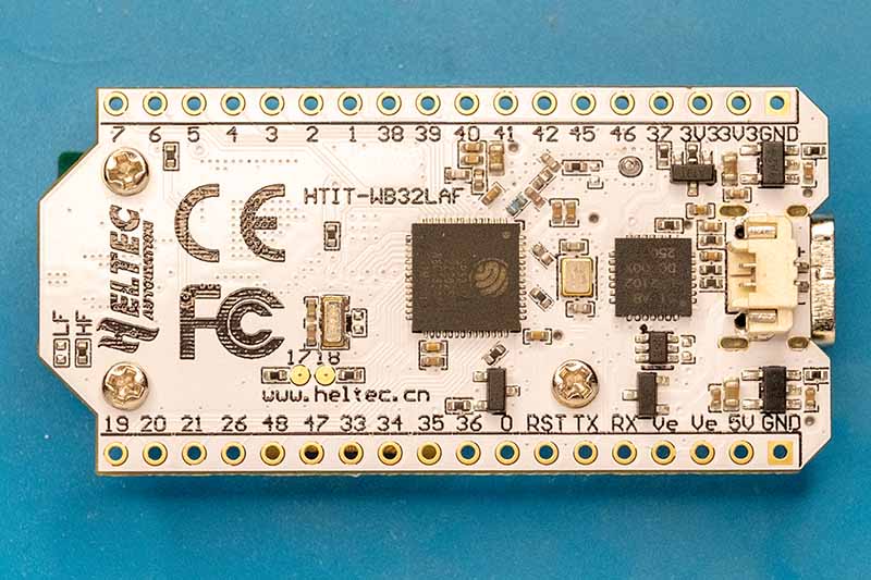
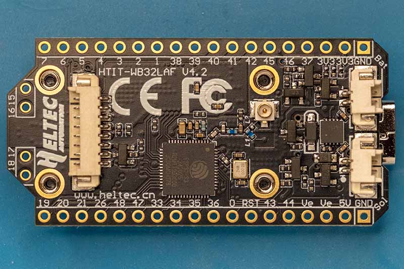
Heltec WiFi LoRa 32 (V3.x & V4)
Originally, I had planned to assemble the hardware for this project myself and simply connect an ESP32 to a Semtech LoRa transceiver module. However, I abandoned this idea when I discovered the Heltec WiFi LoRa 32 boards. These boards integrate a microcontroller, the LoRa chip, and a display, and are available for around €20.
For current LoRa applications, only the V3 and V4 series boards are relevant. Both generations share the same architecture: an ESP32-S3 microcontroller coupled with the current Semtech SX1262 transceiver and a small monochrome display. Nevertheless, there are some differences in the details.
|
|
|
|
|
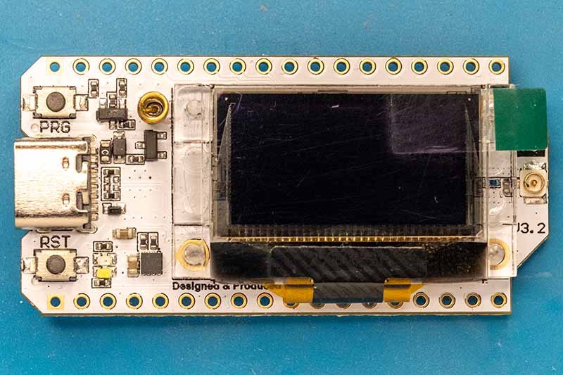
Version 3.x
With V3, Heltec transitioned from its older architecture to the ESP32-S3/SX1262 design. This series saw several hardware revisions:
- V3.0: The basic version. Solid performance, but suffered from increased power consumption in deep sleep mode.
- V3.1: This version improved power management through optimized voltage regulators and LDOs, significantly extending battery life in standby mode.
- V3.2: This revision introduced a TCXO (Temperature Compensated Oscillator). This ensures that the frequency remains stable even under extreme temperature fluctuations (e.g., outdoors in winter), which is essential for LoRaWAN and low bandwidth applications.
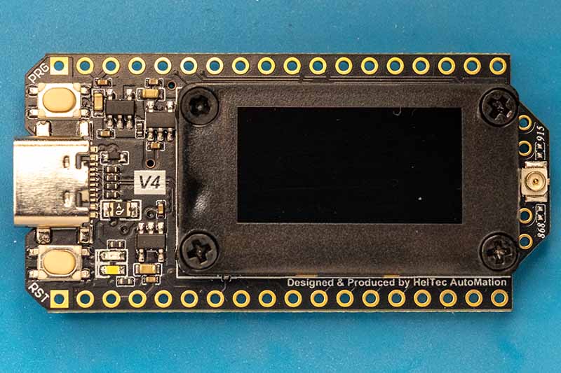
Version 4
Introduced in 2025, V4 largely retains the same form factor but introduces several key improvements for stand-alone operation:
- Transmit power: A new RF power amplifier now allows for up to +28 dBm (approx. 500 mW) (V3: approx. +21 dBm). This provides significant range reserves (subject to regional limitations).
Important: Unlike the V3, this external amplifier must be explicitly activated via software. To prevent the board from remaining in the weak 'bypass mode', it is mandatory to set GPIO 7 (Power Supply/VFEM), GPIO 2 (Chip Enable/CSD), and GPIO 46 (Power Mode/CPS) to HIGH. - Solar management: V4 features a dedicated solar input that directly charges the battery, eliminating the need for separate charging electronics.
- Features: A dedicated port for GNSS (GPS) modules is now integrated. Additionally, the memory has been increased to 16 MB Flash + 2 MB PSRAM to enable more complex applications.
Software-wise, V3 and V4 are largely compatible (both use the ESP32-S3). Unfortunately, the exact version is usually not specified by retailers for V3.x boards.
Semtech SX1262
The SX1262 is an integrated sub-GHz transceiver covering the frequency range of 150 to 960 MHz and supporting modulation for LoRa and (G)FSK. Unlike older generations that primarily operated using registers, the SX1262 is controlled by an internal state machine that accepts commands (opcodes) via SPI.
To implement a driver for this chip, one must first consider the internal logic, the specifics of the hardware interface, and the necessary steps. For more detailed information, I recommend consulting the SX1262 datasheet.
1. The Communication Interface
The communication is based on a classic SPI interface, which has been extended with important handshake mechanisms. The SX1262 acts as a slave and supports clock frequencies of up to 16 MHz. Unlike classic register-based transceivers, where a transaction usually consists only of address and data, the SX1262 uses an instruction architecture. Every interaction begins with an 8-bit opcode that defines what is to be done (e.g., "Write Register," "Set Mode," "Read Buffer")..
The structure of a transaction differs depending on the operation type:
Write Transactions (Commands & Write Register)
This is the simplest case. The host sends the instruction and immediately afterwards the parameters or data:
- NSS Low: The host initiates the transaction.
- OpCode: The host sends the instruction byte (e.g., 0x80 for SetStandby).
- Parameter: The host sends n bytes of parameters (e.g., 0x00 for STDBY_RC).
- NSS High: The rising edge signals to the chip that the instruction is complete and ready to be processed.
Read Transactions (Read Register & Buffer)
The SX1262 requires time to prepare the requested data internally. Therefore, the host must send a NOP (No Operation) or dummy byte after the address before it can read the actual data:
- NSS Low
- OpCode: Host sends 0x1D (Read Register).
- Adresse: Host sends 2 bytes of address (e.g., 0x0740 for Sync Word).
- NOP: Host sends 0x00. During this clock cycle, the SX1262 prepares the data.
- Daten: Host sends further dummy bytes (0x00) to generate the clock signal while the SX1262 outputs the data on the MISO line.
- NSS High
Status-Byte (MISO Return Channel)
While the host sends the opcode and parameters on the MOSI line, the MISO line is not silent. The SX1262 simultaneously sends a status byte back with every transaction (including writes). This byte contains important diagnostic information, such as the current chip mode (e.g., 0x2 for STDBY_RC) and the command status (e.g., 0x4 for Command Error).
BUSY Pin
The most important element for a stable driver is the BUSY pin. Because the SX1262 has an internal processor, instructions are not always processed immediately in real time. The BUSY pin acts as an indicator of the state of this internal state machine.
- HIGH state: The internal processor is busy. This occurs, for example, during waking from sleep mode, PLL calibration, or while processing a complex instruction. In this state, the SPI bus is blocked for write instructions.
- LOW state: The chip is ready (idle) and can receive new instructions.
This means that before every SPI transaction (except for certain status queries), the driver must check the state of the BUSY pin. If a command is sent while BUSY is active, it will be ignored or result in undefined behavior.
2. Multi-function pins (DIO)
To minimize the number of lines required to the microcontroller, the SX1262 offers three flexible digital I/O (DIO) pins. These are not hardwired but can be configured via software to perform various tasks in the RF design.
DIO1: Central interrupt source
For driver development, DIO1 is the most important pin. It functions as a universal interrupt output. Whether a packet was successfully sent (TxDone), data was received (RxDone), or a timeout occurred – all these events are collected in the SX1262's interrupt controller and can be masked onto the DIO1 pin. The SetDioIrqParams command (0x08) controls this mapping.
DIO2: Automatic RF Switch Control
In an RF design, an antenna switch (RF switch) is usually required to switch between the transmit and receive paths. Instead of manually controlling this switch via a microcontroller GPIO, the SX1262 can handle this task. The SetDio2AsRfSwitchCtrl command (0x9D) configures DIO2 to automatically switch to a high level as soon as the transceiver enters transmit (TX) mode. In all other modes (RX, Sleep), it falls back to low. This guarantees precise timing of the antenna switch without latency from the host controller.
DIO3 and Frequency Stability (TCXO)
The DIO3 pin plays a special role that is particularly critical for low-bandwidth LoRa applications: controlling a TCXO (Temperature Compensated Crystal Oscillator).
A conventional crystal oscillator (XTAL) is subject to frequency drift due to temperature fluctuations. Since LoRa signals are often very narrowband (e.g., 125 kHz or lower), even a slight temperature change can cause the receiver to lose the signal. Modern modules (such as the Heltec V3) use a TCXO, which actively compensates for this, but require an active power supply and a settling time.
To save energy, the SX1262 can power the TCXO via the DIO3 pin. The driver uses the command `SetDIO3AsTcxoCtrl` (0x97) for this purpose. This configures the output voltage (e.g., 1.8 V) and a delay time. The SX1262 only activates the voltage at DIO3 when it actually needs the clock signal (e.g., in RX or TX mode). In sleep mode, the TCXO is automatically switched off. Without correct configuration of this pin, a board with TCXO will remain non-functional, as the chip will not receive a base clock.
3. Memory Architecture: The Data Buffer
The SX1262 has a 256-byte RAM area. Unlike a FIFO, this memory is not automatically cleared but retains its contents (except in sleep mode) and must be actively addressed by the driver.
Since transmit and receive operations access the same physical memory, it is the driver's responsibility to partition this area so that TX and RX data do not unintentionally overwrite each other.
Memory Partitioning (SetBufferBaseAddress)
The internal state machine's access to memory is controlled by two pointers, which are configured using the SetBufferBaseAddress (0x8F) command:
- TxBaseAddress: Defines the offset in RAM at which the chip begins reading data for modulation.
- RxBaseAddress: Defines the offset in RAM at which the chip begins writing received data.
Different offsets allow the memory to be logically divided (e.g., TX area in the lower part, RX area in the upper part) to avoid conflicts.
The Transmitting Process (TX)
During transmission, the driver writes the data to an address it selects and informs the chip that this is the starting point for the transfer.
- Setting the pointer: The driver sends `SetBufferBaseAddress` and sets `TxBaseAddress` to the desired offset (e.g., 0x00 or 0x80).
- Writing the data: The `WriteBuffer` command (0x0E) copies the payload data to this offset in memory.
- Defining the length: The `SetPacketParams` command (0x8C) configures the exact payload length. This is essential so the chip knows how many bytes to send starting from `TxBaseAddress`.
- Starting: The `SetTx` command starts the transfer. The chip now reads from `TxBaseAddress`.
The Receive Process (RX)
During reception, the driver allocates a memory area to the chip. However, reading is dynamic based on feedback from the chip, not fixed via the base pointer.
- Memory allocation: Before switching to RX mode, the driver uses SetBufferBaseAddress to set the RxBaseAddress to a free memory area.
- Receive: The chip writes incoming data to RAM starting at this address.
- Metadata query: After the RxDone interrupt, the driver cannot simply read blindly from RxBaseAddress. Instead, the GetRxBufferStatus instruction (0x13) must be executed. This returns two values:
- PayloadLengthRx: The actual number of bytes received.
- RxStartBufferPointer: The exact starting address of the packet in memory.
- Data readout: The driver now reads the data using ReadBuffer (0x1E), using the RxStartBufferPointer reported by the chip as the starting address.
The 256-byte memory behaves circularly. If a read or write operation exceeds address 255, it automatically resumes at address 0. The driver must ensure that packets extending beyond the end of the memory are handled correctly if the upper address range is used.
4. Initialization and Configuration
Initializing the SX1262 requires a strict command sequence, as the interpretation of certain parameters depends on the selected operating mode. After a power-on reset, the chip is in STDBY_RC mode.
Step 1: Defining the Radio Topology
The very first command must be SetPacketType (0x8A). Here, the driver decides whether the chip should operate in LoRa mode (0x01) or FSK mode (0x00). All subsequent commands for modulation and packet structure are interpreted by the chip based on this selection.
Step 2: Configuring the Power Amplifier (PA)
Depending on the transmit power, the SX1262 requires specific control of the PA transistors. The SetPaConfig command (0x95) expects four parameters:
- paDutyCycle: Controls the PA's duty cycle. For +22 dBm, 0x04 is typically used.
- hpMax: Defines the power amplifier (PA) size. For the SX1262, this value must be set to 0x07 to achieve full power.
- deviceSel: Selects the chip type. For the SX1262, this is 0x00 (for the SX1261, it would be 0x01).
- paLut: A reserved value that is always set to 0x01.
Step 3: RF Parameters and Modulation
Next, the frequency (SetRfFrequency 0x86) and the modulation parameters (SetModulationParams 0x8B) are set. For LoRa, this includes the Spreading Factor (SF), the Bandwidth (BW), and the Coding Rate (CR). An important detail here is the "LowDataRateOptimize" bit: For very slow transmissions (high SF, low BW), this bit must be enabled to ensure receiver synchronization.
5. Sending and Receiving
Interaction during operation follows a clear pattern of command, wait time, and interrupt handling..
The Send Cycle (TX)
To send a packet, the driver first writes the payload to internal memory using WriteBuffer (0x0E). Then, the interrupt parameters (SetDioIrqParams) are configured to specify which events (e.g., TxDone) should be signaled. The actual sending process is triggered by SetTx (0x83), where a timeout can optionally be specified. The chip then powers up the power amplifier (PA) and sends the preamble and the data..
Detection that the sending process is complete can be achieved in two ways:
- Interrupt: The chip triggers a signal transition on the configured DIO1 pin. This is efficient because the host microcontroller can sleep during transmission.
- Polling: Alternatively, the driver cyclically queries the internal status register using GetIrqStatus (0x12). Once the TxDone bit is set in the return value, the process is complete.
In both cases, the driver must then clear the interrupt flag using ClearIrqStatus (0x02) to release the chip for the next cycle.
The Receive Cycle (RX)
In receive mode (SetRx 0x82), the chip waits for a valid preamble. Once detected, it synchronizes and receives the packet.
Successful reception and error signaling are analogous to sending:
- Interrupt: The RxDone interrupt is triggered at DIO1 as soon as a packet is received completely and (with CRC enabled) without errors.
- Polling: The driver periodically reads the IrqStatus and checks whether the RxDone flag (or CrcErr) has been set.
Once a packet is ready, the driver must perform two steps:
- Get status: The GetRxBufferStatus command (0x13) returns the packet length and the start offset in the buffer.
- Read data: The ReadBuffer command (0x1E) reads the data at the previously determined address.
Errors (e.g., CRC errors) are also handled via flags in the status register (CrcErr).
SX1262 Driver for the ESP32
Based on this information, I started implementing an SX1262 driver for the ESP32. The driver is very simple but supports all the basic functions for LoRa communication. The code was developed and tested with Heltec WiFi LoRa 32 V3.x and V4 boards, but with appropriate configuration, it should work with any SX1262 board. Of course, I could have simply used a pre-made driver, but the learning experience is significantly greater when developing one yourself.
Driver Architecture
The driver essentially consists of three parts:
- Hardware Initialization - SPI bus and GPIO configuration
- Radio Configuration - LoRa parameters and modem settings
- Communication - Sending and receiving packets
This separation makes the code clear and allows for step-by-step initialization of the driver and switching between different operating modes. The implementation closely follows the SX1262 datasheet and the Semtech application notes.
API in Detail
Initialization and Configuration
sx1262_init_bus()
This function initializes the SPI bus and configures the GPIO pins for communication with the SX1262.
Functionality:
- Configures the GPIO pins for BUSY, DIO1 (as an input), and RESET (as an output)
- Initializes the SPI2 bus
- Registers the SX1262 device on the SPI bus
This function must be called first, before any other driver function is used.
sx1262_init_radio()
After bus initialization, the radio itself must be configured. This function performs a complete hardware reset, bringing the SX1262 to a defined initial state.
Functionality:
- Performs a hardware reset (via the RESET pin)
- Waits for a BUSY signal
- Puts the chip in standby mode (STDBY_XOSC)
- Configures the TCXO (Temperature Compensated Crystal Oscillator) for 3.3V and a 5ms timeout
- Configures DIO2 as an RF switch (for automatic TX/RX switching)
- Sets the voltage regulator mode (DC-DC + LDO)
- Performs a full calibration (0x7F = all blocks)
- Configures the fallback mode (chip reverts to STDBY_XOSC after TX/RX)
The SX1262 initialization is therefore in a separate function, as it only needs to be called on a cold start.
sx1262_wakeup()
If the SX1262 was in sleep mode and the configuration needs to be retained (warm restart), this function can be used.
Functionality:
- Wakes the chip by applying NSS Low
- Waits for a BUSY signal
- Verifies that the configuration has been retained (by reading the packet type)
This function is particularly important for devices that enter deep sleep between transmissions. A warm restart saves time and energy compared to a complete re-initialization.
sx1262_configure()
This is the central configuration function that sets all LoRa parameters.
Parameter: Pointer to the sx1262_config_t structure
typedef struct {
    sx1262_modem_mode_t modem_mode;  // LoRa or FSK
    uint32_t frequency;              // Frequency in Hz
    int8_t tx_power;                 // TX Power in dBm

    // LoRa specific parameters
    sx1262_bandwidth_t bandwidth;    // Bandwidth (LoRa only)
    uint8_t spreading_factor;        // Spreading Factor 5-12 (LoRa only)
    sx1262_coding_rate_t coding_rate;// Coding Rate (LoRa only)
    bool iq_inverted;                // IQ inverted (LoRa only)
    bool rx_gain_boosted;            // true = Boosted RX Gain (+3dB sensitivity)

    // FSK specific parameters
    uint32_t fsk_bitrate;            // Bitrate in bps (FSK only)
    uint32_t fsk_fdev;               // Frequency deviation in Hz (FSK only)
    sx1262_fsk_rx_bw_t fsk_rx_bw;    // RX Bandwidth (FSK only)
    sx1262_fsk_mod_shaping_t fsk_shaping; // Pulse shaping (FSK only)

    // Common parameters
    uint16_t preamble_length;        // Preamble length
    uint8_t payload_length;          // Payload length (0 = variable)
    bool crc_on;                     // CRC enabled
    uint16_t sync_word;              // LoRa Sync Word (0x1424 = public, 0x3444 = private)
} sx1262_config_t;
Functionality: This function performs comprehensive configuration:
- Set Packet Type: LoRa or FSK
- Set Frequency: Calculates the register value from the frequency in Hz
- Image Calibration: Calibrates the frequency band for optimal performance
- PA Configuration: Sets the power amplifier parameters based on the desired transmit power
- OCP Configuration: Sets the overcurrent protection according to the transmit power
- TX Parameters: Configures transmit power and ramp time
- Modulation Parameters: Sets SF, BW, CR, and Low Data Rate Optimization
- Packet Parameters: Configures preamble, payload length, CRC, and IQ
- Workarounds: Applies manufacturer-recommended corrections (IQ polarity, 500 kHz BW)
- Sync Word: Sets the LoRa sync word for network separation
- RX Gain: Selects between power save and boosted mode
This function puts the chip into standby mode. After sx1262_configure() the radio is ready to transmit or receive.
Send and Receive
sx1262_send()
Sends a LoRa packet.
Parameters:
data: Pointer to data to be sentlen: Length of data in bytes (max. 255)
Functionality:
- Puts the chip in standby mode
- Writes data to the SX1262's TX buffer
- Configures the TX timeout (0xFFFFFF = no timeout)
- Starts the transmission
- Waits for the TX_DONE interrupt (polling)
- Automatically returns to standby mode (fallback mode)
The function blocks until the transmission is complete. The data is copied internally, and the caller can immediately reuse the buffer.
sx1262_receive()
Receives a LoRa packet in polling mode (blocking).
Parameters:
data: Pointer to receive bufferlen: Pointer to buffer size (input) / received bytes (output)timeout_ms: Timeout in milliseconds (0 = Continuous RX with a 60s limit)
Functionality
- Sets chip to standby
- Configures RX timeout
- Starts RX mode
- Continuously polls the IRQ status (every 1 ms)
- On RX_DONE: Reads buffer status and data
- On TIMEOUT or CRC_ERROR: Aborts with the corresponding error
This function blocks the task until a packet is received or the timeout expires. The buffer must be large enough for the expected packet – there is no overflow check!
sx1262_start_receive_async()
Starts asynchronous receive mode with interrupt handling.
Parameters:
callback: Callback function that is called upon packet reception
typedef void (*sx1262_rx_callback_t)(uint8_t *data, uint8_t len,
sx1262_packet_status_t *status);
The callback function receives:
data: Pointer to received data (buffer reused!)len: Number of bytes receivedstatus: Pointer to packet status (RSSI and SNR)
Functionality:
- Puts the chip in standby mode
- Configures DIO1 as a GPIO interrupt (positive edge)
- Creates a high-priority FreeRTOS task (10)
- Installs the ISR handler for DIO1
- Configures the IRQ mask (RX_DONE, CRC_ERROR, HEADER_ERROR)
- Starts continuous RX mode (0xFFFFFF)
Process:
- The ISR is triggered when DIO1 is high.
- The ISR sends a notification to the RX task.
- The RX task reads the IRQ status via SPI.
- When RX_DONE is present: Reads the data and calls the callback.
- The RX task reactivates RX mode (continuous loop).
The callback runs in the task context (not ISR!), therefore blocking operations are allowed. The data buffer is reused - copy it if necessary!
sx1262_stop_receive_async()
Stops the asynchronous receive mode.
Functionality:
- Removes the ISR handler from DIO1
- Disables GPIO interrupts
- Clears the RX task
- Puts the chip in standby mode
After stopping, the receive function must be called again to resume receiving.
Helper Functions
sx1262_sleep()
Puts the SX1262 into sleep mode (warm start configuration).
Functionality:
- Sends a sleep command with configuration 0x04 (warm start).
- Registers are retained during a warm start.
- Power consumption: ~1.6 µA
Typically called before the ESP32 enters deep sleep. After waking up, operation can be continued withsx1262_wakeup() .
sx1262_standby()
Puts the chip into standby mode (STDBY_XOSC).
Functionality:
- Stops all radio operations.
- TCXO remains active.
- Power consumption: ~1.2 mA
Called automatically by many functions. Can be used manually to interrupt running operations.
sx1262_get_rssi()
Reads the current RSSI (Received Signal Strength Indicator) value.
Return value:
- RSSI in dBm (typically -120 to 0 dBm)
- -999 for errors
Useful only in RX mode or immediately after packet reception.
sx1262_get_packet_status()
Reads detailed information about the last received packet.
Parameters:
status: Pointer to thesx1262_packet_status_tstructure
typedef struct {
    int16_t rssi;  // RSSI in dBm
    int8_t snr;    // SNR in dB
} sx1262_packet_status_t;
sx1262_get_chip_info()
Outputs chip information via the ESP logger (debug function).
Functionality:
- Reads status registers
- Outputs information to the console
Code examples
Example 1: Basic Initialization
#include "sx1262.h"

void app_main(void){
    // Phase 1: Initialize bus
    esp_err_t ret = sx1262_init_bus();
    if (ret != ESP_OK) {
        ESP_LOGE("APP", "Bus initialization failed");
        return;
    }

    // Phase 2: Initialize radio
    ret = sx1262_init_radio();
    if (ret != ESP_OK) {
        ESP_LOGE("APP", "Radio initialization failed");
        return;
    }

    ESP_LOGI("APP", "SX1262 initialization complete");
}
Example 2: LoRa configuration
void configure_lora(void){
    sx1262_config_t config = {
        .modem_mode = SX1262_MODEM_LORA,
        .frequency = 868000000,         // 868 MHz (EU)
        .tx_power = 14,                 // 14 dBm TX power

        // LoRa parameters
        .bandwidth = LORA_BW_125,       // 125 kHz bandwidth
        .spreading_factor = 7,          // SF7
        .coding_rate = LORA_CR_4_5,     // CR 4/5
        .iq_inverted = false,           // Standard IQ
        .rx_gain_boosted = false,       // Power Save RX Gain

        // Packet parameters
        .preamble_length = 8,           // 8 symbol preamble
        .payload_length = 0,            // Variable length
        .crc_on = true,                 // CRC enabled
        .sync_word = 0x3444             // Private network
    };

    esp_err_t ret = sx1262_configure(&config);
    if (ret != ESP_OK) {
        ESP_LOGE("APP", "Configuration failed");
        return;
    }

    ESP_LOGI("APP", "LoRa configured: SF7, BW125, CR4/5, 868MHz");
}
Parameter Explanation:
- frequency: The ISM frequency, typically 868 MHz in Germany
- tx_power: The transmit power in dBm. The SX1262 supports -9 to +22 dBm; 2-14 dBm is practical for short distances and 14-22 dBm for long distances
- bandwidth: Smaller bandwidth = higher sensitivity, but longer transmission time
- spreading_factor: SF7 = fast/short range, SF12 = slow/long range
- coding_rate: CR 4/5 = less overhead, CR 4/8 = more error correction
- rx_gain_boosted: false = ~1.2 mA power consumption, true = ~1.8 mA but +3 dB sensitivity
- sync_word: 0x3444 for private networks, 0x1424 for LoRaWAN public networks
Example 3: Simple sending
void send_message(void)
{
    char message[] = "Hello LoRa!";

    esp_err_t ret = sx1262_send((uint8_t*)message, strlen(message));

    if (ret == ESP_OK) {
        ESP_LOGI("APP", "Message sent successfully");
    } else if (ret == ESP_ERR_TIMEOUT) {
        ESP_LOGW("APP", "TX Timeout");
    } else {
        ESP_LOGE("APP", "TX Failed");
    }
}
Example 4: Blocking reception (polling)
void receive_message_blocking(void){
    uint8_t rx_buffer[255];
    uint8_t rx_len = sizeof(rx_buffer);

    ESP_LOGI("APP", "Waiting for packet (5s timeout)...");

    esp_err_t ret = sx1262_receive(rx_buffer, &rx_len, 5000);

    if (ret == ESP_OK) {
        ESP_LOGI("APP", "Received %d bytes", rx_len);

        // Print data as string (if it is text)
        rx_buffer[rx_len] = '\0';
        ESP_LOGI("APP", "Data: %s", rx_buffer);

        // Read RSSI and SNR
        sx1262_packet_status_t status;
        sx1262_get_packet_status(&status);
        ESP_LOGI("APP", "RSSI: %d dBm, SNR: %d dB", status.rssi, status.snr);

    } else if (ret == ESP_ERR_TIMEOUT) {
        ESP_LOGW("APP", "RX Timeout - no packet received");
    } else if (ret == ESP_ERR_CRC_ERROR) {
        ESP_LOGW("APP", "CRC Error");
    } else {
        ESP_LOGE("APP", "RX Failed");
    }
}
Ideal for simple receivers or when the ESP32 only receives sporadically. The task blocks while waiting.
Example 5: Asynchronous reception with interrupts
// Callback function for received packets
void on_packet_received(uint8_t *data, uint8_t len,
                       sx1262_packet_status_t *status){
    ESP_LOGI("RX", "Packet received: %d bytes", len);
    ESP_LOGI("RX", "RSSI: %d dBm, SNR: %d dB", status->rssi, status->snr);

    // Process data
    // IMPORTANT: Copy data if needed later!
    char message[256];
    memcpy(message, data, len);
    message[len] = '\0';
    ESP_LOGI("RX", "Message: %s", message);

    // Further processing...
}

void start_async_receiver(void){
    esp_err_t ret = sx1262_start_receive_async(on_packet_received);

    if (ret == ESP_OK) {
        ESP_LOGI("APP", "Async RX mode started");
        ESP_LOGI("APP", "Receiver is now listening continuously");
    } else {
        ESP_LOGE("APP", "Failed to start async RX");
    }
}

void stop_async_receiver(void){
    sx1262_stop_receive_async();
    ESP_LOGI("APP", "Async RX mode stopped");
}
Ideal for gateways or receivers that need to listen continuously. The ESP32 can perform other tasks in the meantime. The callback runs in its own high-priority task. Time-critical processing is possible, but longer operations should be offloaded to a separate task.
Example 6: Deep Sleep Sensor Node
This example shows an energy-efficient sensor node that periodically sends measurement data and enters deep sleep mode between transmissions.
#include "sx1262.h"
#include "esp_sleep.h"
#include "esp_log.h"

#define SLEEP_DURATION_SEC 300  // 5 minutes between measurements

// Structure for sensor data
typedef struct {
    float temperature;
    float humidity;
    uint32_t battery_mv;
} sensor_data_t;

// Simulated sensor measurement
sensor_data_t read_sensors(void)
{
    sensor_data_t data;
    data.temperature = 22.5;  // In real application: BME280, DHT22, etc.
    data.humidity = 65.0;
    data.battery_mv = 3700;
    return data;
}

RTC_DATA_ATTR bool sx1262_is_configured = false;

void app_main(void) {

    // Initialize bus (must always be done)
    esp_err_t ret = sx1262_init_bus();
    if (ret != ESP_OK) {
        ESP_LOGE("APP", "Bus init failed");
        return;
    }

    bool radio_ready = false;

    // Was the ESP32 in deep sleep?
    if (esp_sleep_get_wakeup_cause() == ESP_SLEEP_WAKEUP_TIMER && sx1262_is_configured) {

        ESP_LOGI("APP", "Woke up from deep sleep. Attempting warm start...");

        // Wake up SX1262 (NSS Toggle)
        if (sx1262_wakeup() == ESP_OK) {
            ESP_LOGI("APP", "Warm start successful! Configuration retained.");
            radio_ready = true;
        } else {
            ESP_LOGW("APP", "Warm start failed (SX1262 has amnesia).");
            // radio_ready remains false -> Fallback to cold start
        }
    }

    // Fallback / Cold start logic
    if (!radio_ready) {
        ESP_LOGI("APP", "Performing cold start (Hard-Reset & Calibration)...");

        // The expensive, slow part:
        sx1262_init_radio();

        // Resend configuration
        sx1262_config_t cfg = {
            .modem_mode = SX1262_MODEM_LORA,
            .frequency = 869525000,
            .tx_power = 22,
            .spreading_factor = 7,
            .bandwidth = LORA_BW_125,
            .coding_rate = LORA_CR_4_5,
            .preamble_length = 8,
            .crc_on = true
        };
        sx1262_configure(&cfg);

        // Remember for next time!
        sx1262_is_configured = true;
    }

    // --- Chip is ready from here on ---

    // Read sensors
    sensor_data_t sensor_data = read_sensors();

    ESP_LOGI("APP", "Temperature: %.1f°C", sensor_data.temperature);
    ESP_LOGI("APP", "Humidity: %.1f%%", sensor_data.humidity);
    ESP_LOGI("APP", "Battery: %lu mV", sensor_data.battery_mv);

    // Pack data into packet
    char payload[64];
    snprintf(payload, sizeof(payload),
             "T:%.1f,H:%.1f,BAT:%lu",
             sensor_data.temperature,
             sensor_data.humidity,
             sensor_data.battery_mv);

    // Send LoRa packet
    ESP_LOGI("APP", "Sending data...");
    ret = sx1262_send((uint8_t*)payload, strlen(payload));

    if (ret == ESP_OK) {
        ESP_LOGI("APP", "Data sent successfully");
    } else {
        ESP_LOGE("APP", "Send failed: %d", ret);
    }

    // Radio in sleep mode (Warm Start)
    sx1262_sleep();

    // ESP32 in deep sleep
    ESP_LOGI("APP", "Going to sleep for %d seconds", SLEEP_DURATION_SEC);
    esp_deep_sleep(SLEEP_DURATION_SEC * 1000000ULL);
}
Notes:
- After deep sleep and a successful warm start, you save approximately 50ms and 0.5mA.
- For even longer runtime: Increase SF (SF12), reduce TX power (e.g., by 10dBm).
- With a poor connection: Use SF12, but this significantly increases airtime.
Example 6: Thread Safety
The driver is NOT thread-safe. If multiple tasks access the radio simultaneously, you must serialize this using a mutex.
static SemaphoreHandle_t lora_mutex = NULL;

void init_lora_mutex(void)
{
    lora_mutex = xSemaphoreCreateMutex();
}

void safe_send(uint8_t *data, uint8_t len)
{
    if (xSemaphoreTake(lora_mutex, pdMS_TO_TICKS(1000)) == pdTRUE) {
        sx1262_send(data, len);
        xSemaphoreGive(lora_mutex);
    }
}
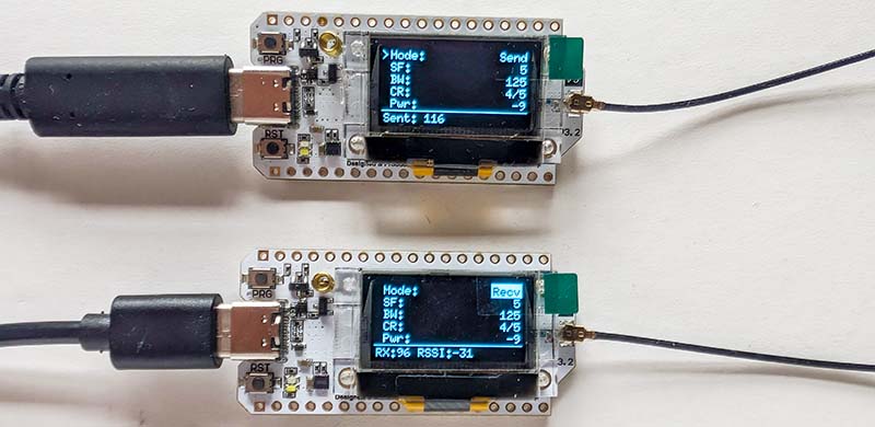
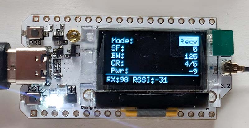
LoRa Test Tool for Heltec WiFi LoRa 32
To test the driver, I developed a small tool for the Heltec boards that allows you to test communication between the boards. The most important parameters can be set via the small display and the PRG button:
- Mode: Transmit/Receive
- Spreading Factor: 5 - 12
- Bandwidth: 125 kHz, 250 kHz, 500 kHz
- Coding Rate: 4/5, 4/6, 4/7, 4/8
- Transmit Power: -9 dBm to 22 dBm
The navigation is structured as follows:
┌────────────────────────────┐
│ >Mode: Send           [*]  │ ← Active menu item (>)
│  SF: 7                     │   Edit mode ([inverted])
│  BW: 125                   │
│  CR: 4/5                   │
│  Pwr: 14                   │
│ ────────────────────────── │
│ TX: 42                   * │ ← Status: Packets + transmit indicator
└────────────────────────────┘

In receive mode:
┌────────────────────────────┐
│  Mode: Recv                │
│  SF: 7                     │
│  BW: 125                   │
│  CR: 4/5                   │
│  Pwr: 14                   │
│ ────────────────────────── │
│ RX:15 RSSI:-85             │ ← Received packets + RSSI
└────────────────────────────┘
Navigation is accomplished using short and long clicks via the PRG button on the board:
Left side (menu navigation)
- Short click
- Jumps to the next menu item
- Cyclical: Mode → SF → BW → CR → Power → Mode
- Long press
- Switches to edit mode (right side)
- Current value is displayed inverted
Right side (edit values)
- Short click
- Moves to the next value (cycles through the options)
- Instantly updates the LoRa configuration
- Long press
- Exits edit mode
- Returns to menu navigation (left side)
This tool makes it very easy to test the range of LoRa, for example. Since no connection to a PC is required, the setup can be operated portably with a power bank. You place a transmitter in a fixed location and walk around the area with the receiver.
The tool allows you to observe live how the parameters affect performance: A higher Spreading Factor (SF) increases the range, but also drastically extends the transmission time. This provides a direct sense of the balance between range and speed.
Additionally, different antennas and positions can be tested. In receive mode (Recv), the display shows the RSSI value (signal strength) of each received packet, and the built-in LED briefly illuminates. This allows you to see immediately whether a new antenna actually provides a gain or whether an unfavorable positioning attenuates the signal too much.
The code for the test tool, including the SX1262 driver, is available on GitHub, as always.
Conclusion
It was once again very exciting to delve into a completely new topic. The underlying idea was the option of using LoRa for the weather station. The Heltec boards would make setting up the sensors very easy. With a CrowPanel Advance and the LoRa module, there would also be a good solution for receiving the sensor data. The problem is that I don't really need such a long range in the city. ESP-NOW is perfectly adequate for my apartment. But maybe I'll think of something else that would be useful...