Switching LED strips and other loads with the ESP32
According to the Espressif data sheet, one GPIO pin of the ESP32 can drive a maximum of 40 mA. This is just strong enough to control a single LED. For my aquarium lighting, however, I now had to control LEDs with a total of about 20 watts. In order to be able to control such loads with the ESP32, at least one more transistor is required that can handle these high currents and can also be switched with a voltage of 3.3 volts, as this voltage is provided at the pins of the ESP32. I would now like to introduce you to some variants that I have tried out myself and briefly describe whether they are at all suitable for this task.

The transistors used
There are many descriptions on the Internet of how to control LED strips or other loads with a microcontroller. The following transistors are frequently used for this purpose:
- TIP120 : Darlington-Transistor, NPN, 60V, 5A, 65W
- IRFZ44N : MOSFET, N-Channel, 55V, 49A, 94W
- IRLZ44N : MOSFET, N-Channel, 55V, 47A, 110W
- IRF3708 : MOSFET N-Channel, 30V, 62A, 87W
The maximum values show immediately that these transistors offer more than enough power for LED lighting. The types are two different groups of transistors, the Darlington transistors and the MOSFETs.
Darlington-Transistor
A Darlington transistor, named after its inventor Sidney Darlington, is a special type of bipolar transistor. It consists of two transistors that are internally interconnected. A Darlington transistor offers high current amplification and is often used when a small control voltage or current change requires a large current amplification.
The two transistors in a Darlington pair are connected in series. The base current of the first transistor controls the second transistor. As a result, the total amplification factor is the product of the amplification factors of both transistors. This allows a Darlington transistor to provide a very high current gain, making it very useful in applications such as power amplifiers and switching elements in control systems.
MOSFET
MOSFETs (metal-oxide-semiconductor field-effect transistors) are transistors based on the field-effect principle. They control the current flow between their source and drain terminals by utilizing an electric field effect at the gate terminal. There are two main types of MOSFETs: N-channel and P-channel. N-channel MOSFETs become conductive when a positive gate voltage is applied, while P-channel MOSFETs become conductive when a negative gate voltage is applied. MOSFETs are known for their low input current, which allows them to be used efficiently in low-power circuits.
The gate-source voltage is the difference between the voltage at the gate terminal (VG) and the voltage at the source terminal (VS) of a MOSFET. It determines whether the MOSFET is switched on or off. Within a certain range, the MOSFET switches on and enables the flow of current between the source and drain; outside this range, the MOSFET remains switched off.
Logic-level MOSFETs are special MOSFETs that are sufficiently conductive at common logic levels (e.g. 5 V or 3.3 V) in digital circuits. This allows them to be controlled directly by microcontrollers without the need for additional driver stages. Logic-level MOSFETs are important for the integration of MOSFETs into digital circuits and facilitate circuit development in applications such as switching power supplies, motor controllers and other electronic systems.
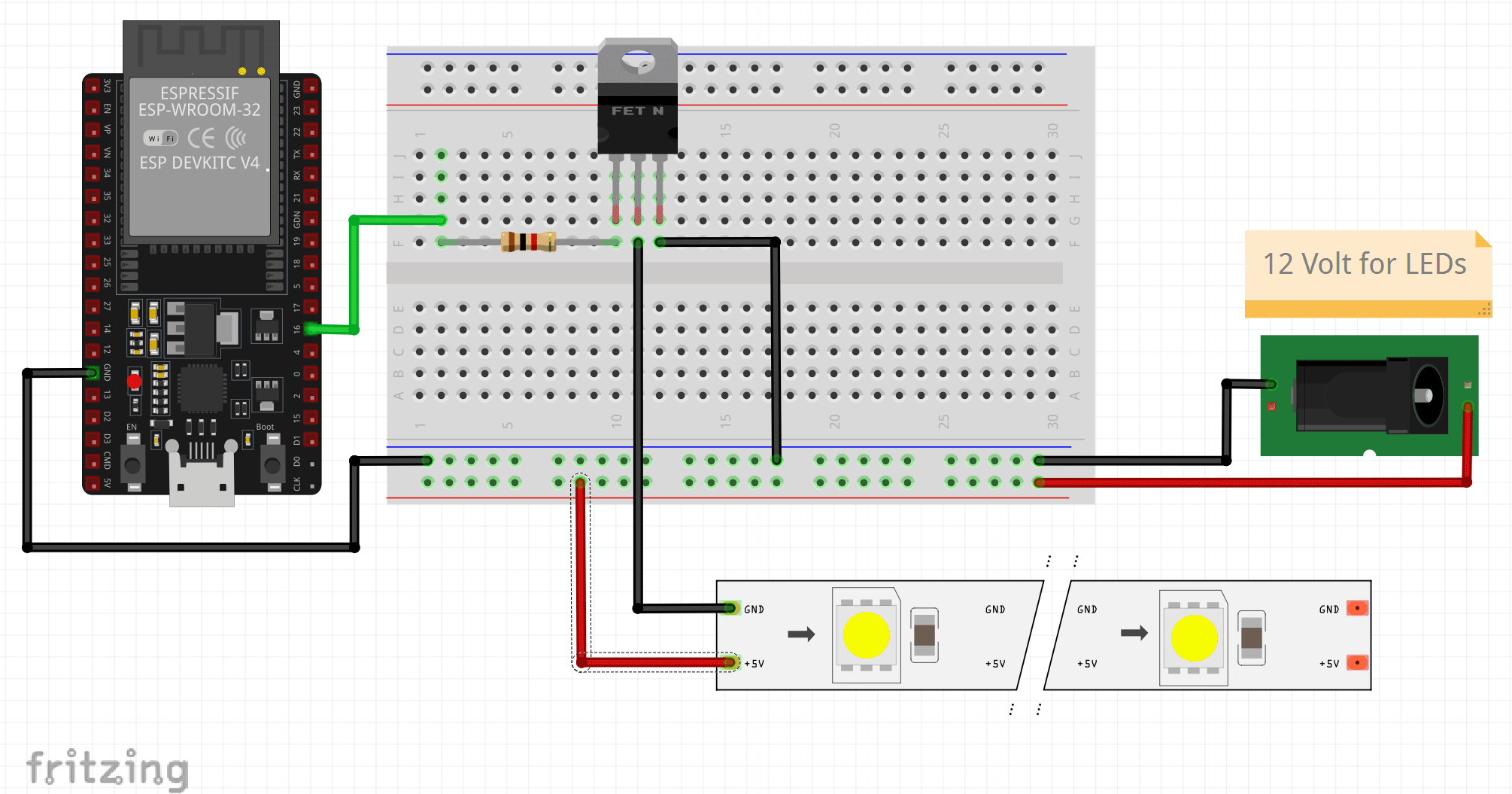
The test setup
Fortunately, the pin assignment is identical for all transistors, i.e. the base of the TIP120 corresponds to the gates of the MOSFETs and collector/emitter correspond to drain/source. The following structure can therefore be used for all four transistors. I use the ESP32-DevKitC V4 to control them. In this case, I use port 16 as the GPIO port. The supply voltage for the LEDs is 12 volts.
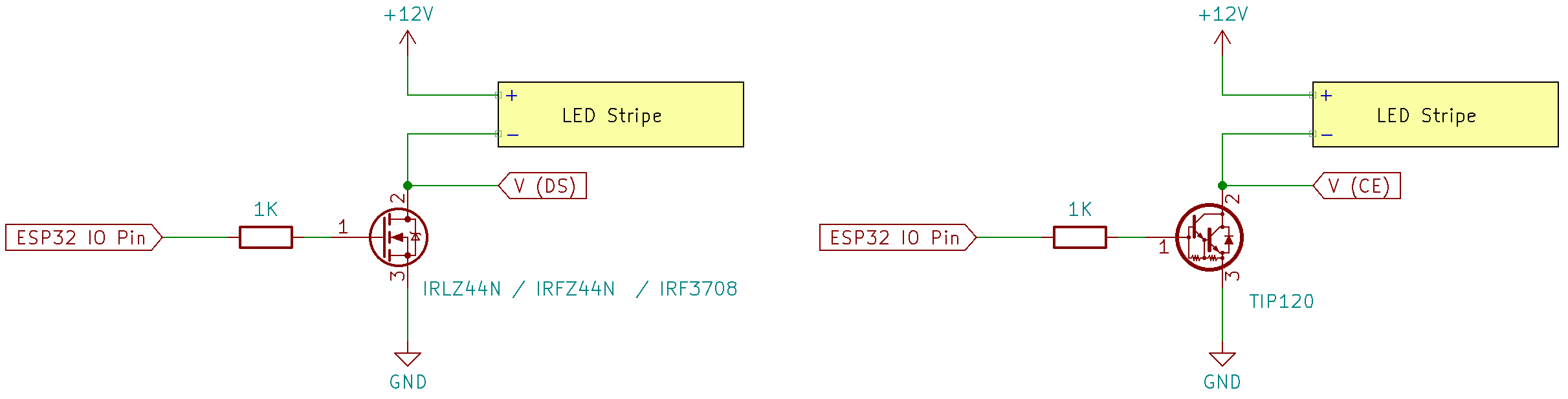
The corresponding circuit diagrams are shown in the following figure. The voltage that drops across the transistor when the input is at logic "1" is measured at the measuring points VDS and VCE. This voltage should be as low as possible, as the transistor should behave like a switch. Ideally, 0 volts would be measured here.
The result
The following table shows the measurement results. The two columns on the right, ILED and P, are the values displayed by the power supply unit, i.e. how much current actually flows through the LED strips and the power output. I will explain what the last line in the table means below.
| VDS / VCE | ILED | P | |
| TIP120 | 924 mV | 1.33 A | 15.9 W |
| IRFZ44N | 5000 mV | 0.002 A | 0.024 W |
| IRLZ44N | 240mV | 1.77 A | 21.4 W |
| IRF3708 | 54 mV | 1.81 A | 21.7 W |
| IRFZ44N & BC547 | 44 mV | 1.82 A | 21.8 W |
Although the TIP120 can supply the LED strips with sufficient power, there is a relatively high voltage drop across the transistor. This is not a problem specific to the TIP120 but applies to all bipolar transistors. As a result, a power of 924mV x 1.33A = 1.22 W is converted into heat at the TIP120. In my test, it also became correspondingly hot and I would not operate it in the long term without a heat sink.
The IRFZ44N fails the test completely. However, this is no surprise, as this type is not a logic-level MOSFET. The IRFZ44N only switches fully from a gate voltage of 7 volts. However, I will explain how to use the IRFZ44N in a moment.
The logic-level MOSFETs IRLZ44N and IRF3708 work without any problems, whereby the latter can deliver slightly more power to the LEDs due to the lower voltage drop.
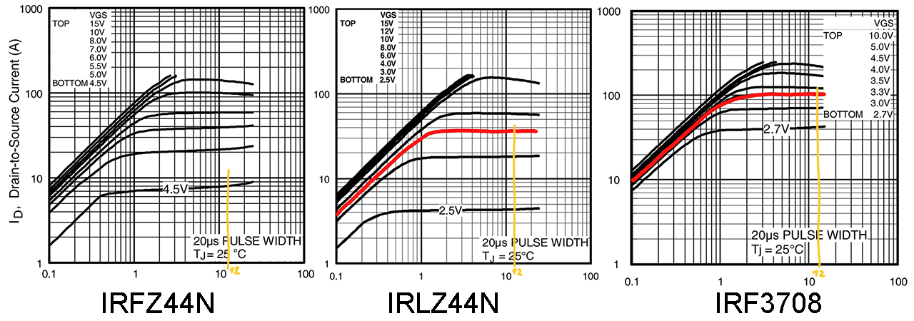
A look at the data sheets confirms the measurements. The following three diagrams show the relationship between gate voltage, source-drain voltage and source-drain current. There is not even a line for the IRFZ44N in the diagram, as it is not designed for such a low voltage.
Finally, I would like to show how the IRFZ44N can be controlled with a simple BC547 NPN bipolar transistor. The circuit diagram looks like this:
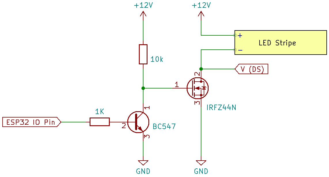
However, this solution also has a disadvantage. The signal is inverted by the BC547. This can be easily solved by changing the logic in the software, but there is still the problem that the LEDs would light up briefly when switching on until the ESP32 sets the output to a defined value.
Conclusion
The result clearly shows that the IRF3708 or the IRLZ44N are best suited for controlling an LED strip. I cannot quite understand why the TIP120 is still recommended in many forums. Of course, there are countless other MOSFETs that are suitable for this purpose. Basically, they should be logic-level MOSFETs that also work at 3.3 volts and not only at 5 volts, as is the case with the Arduino, for example. If in doubt, a look at the data sheet will help.