The Lunyee 3018 Pro Ultra: The Perfect Entry into the World of CNC!
About six years ago, I bought my first 3D printer and I was immediately hooked. The possibilities you have with a device like that are virtually limitless. Since then, I've completed numerous projects: from practical household gadgets and spare parts to more complex mechanical constructions.
But one thing always remained the same: in the end, what came out of the machine was plastic. For many applications, that's perfectly fine, often even ideal. But for the Zyklochron, an ESP32-based mechanical clock, I wanted to create an enclosure out of wood.
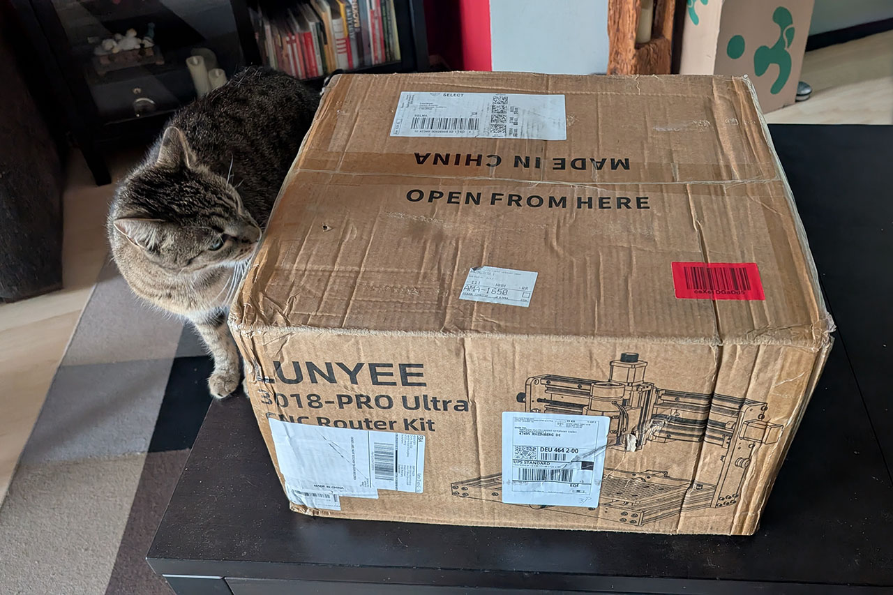
That's why I've now gotten myself a small CNC mill: the Lunyee 3018 Pro Ultra (Affiliate Link). Until recently, I knew almost nothing about CNC machining. In this article, I'll show you the machine, my first steps, and how I managed to successfully mill my first part.
Why the Lunyee 3018 Pro Ultra?
After I decided to buy a CNC mill, I first did some research on the topic. The selection of CNC mills is huge, and the price range extends from about 200 euros to many thousands of euros. A friend who studied mechanical engineering recommended a model from Stepcraft, for example, but even the smallest model costs 2,000 euros.
On the other hand, I didn't want a toy. For such purchases, I generally follow the approach: start simple, upgrade later. That means starting with an affordable, solid device and then moving on to a more professional model if I hit its limits or if the hobby really sticks with me long-term. These considerations and a lot of research finally led me to the Lunyee 3018 Pro Ultra.
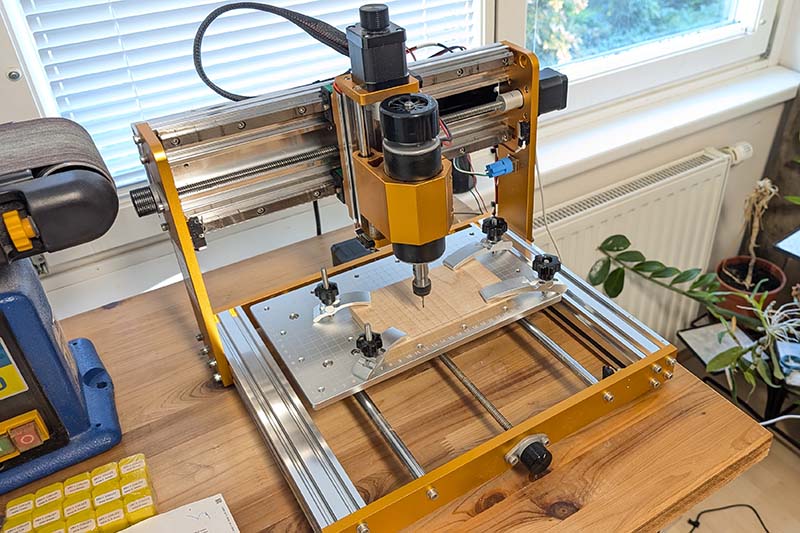
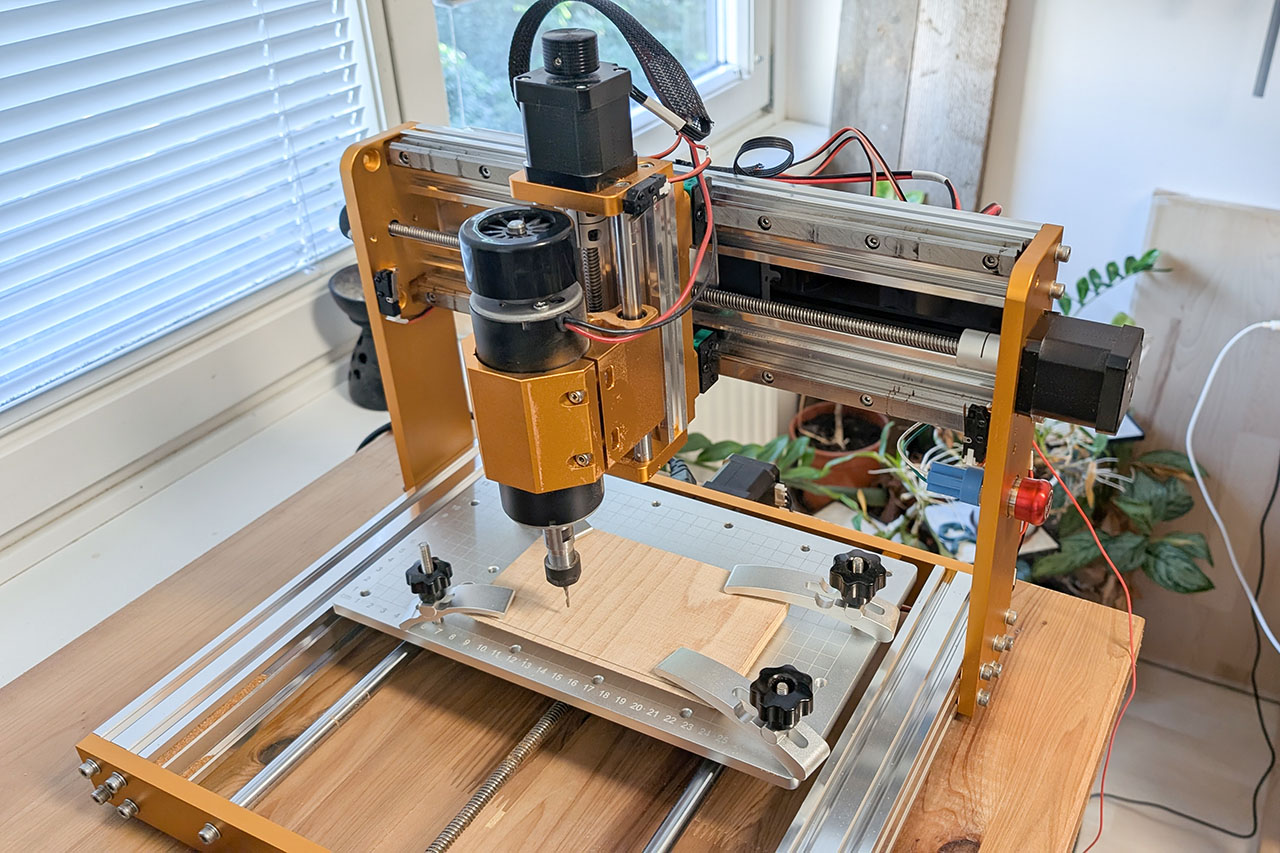
What convinced me about this CNC mill was, above all, the value for money. For 450 euros, you get a compact CNC mill with a metal frame, a powerful 500W spindle, and a lot of accessories, so you can get started right after assembly. This includes, for example, a few end mills, clamps, a Z-probe sensor, and an LCD control panel. Of course, the 3018 is no comparison to an industrial mill, but for my current needs, it's more than sufficient. Here are the most important technical specifications of the Lunyee 3018 Pro Ultra:
| Working Area (XYZ) | 300 × 180 × 80 mm |
| Overall Dimensions | 422 x 414 x 350mm |
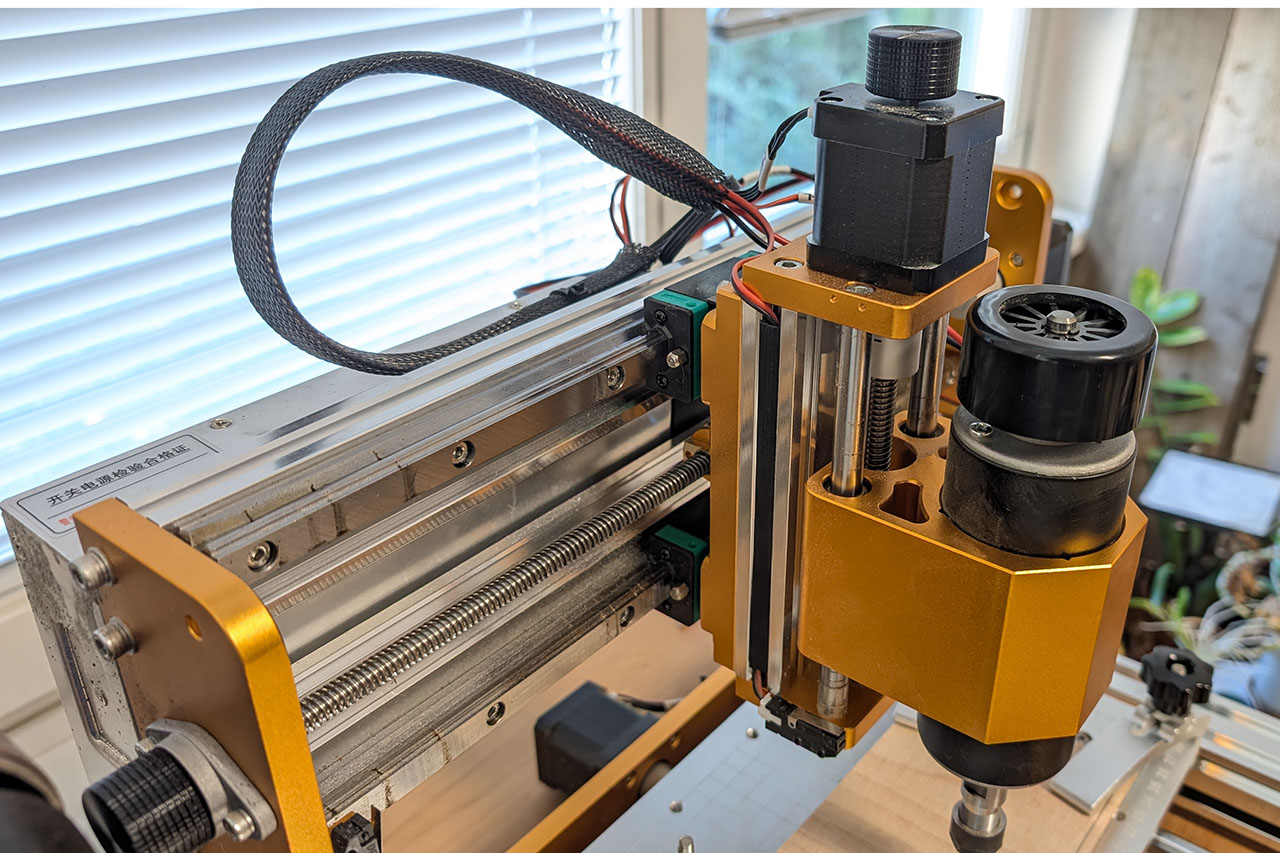
| Frame Material | Aluminum profiles, Y-axis 40x40 mm, X-axis 20x40 mm |
| Spindle | 500W spindle, air-cooled, 10,000 RPM |
| Collet Chuck | ER11 – compatible with many end mill diameters |
| Controller | GRBL 1.1f compatible controller, controllable via USB or offline |
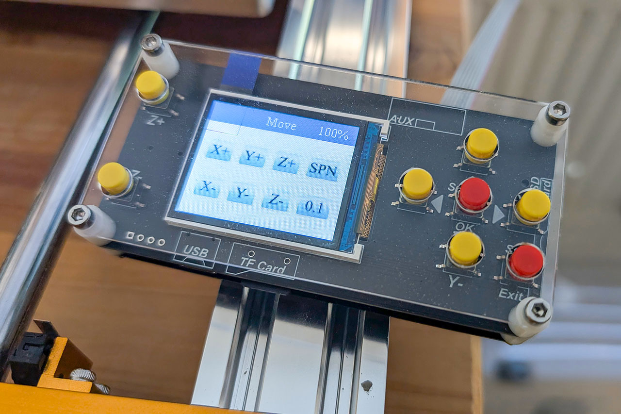
| Offline-Controller | Small LCD control panel for milling without a PC |
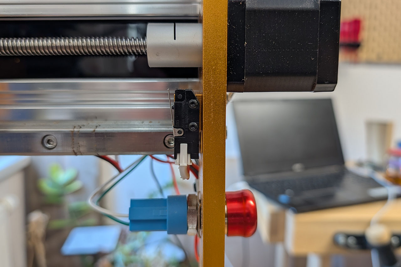
| Limit Switches | Pre-installed on all axes |
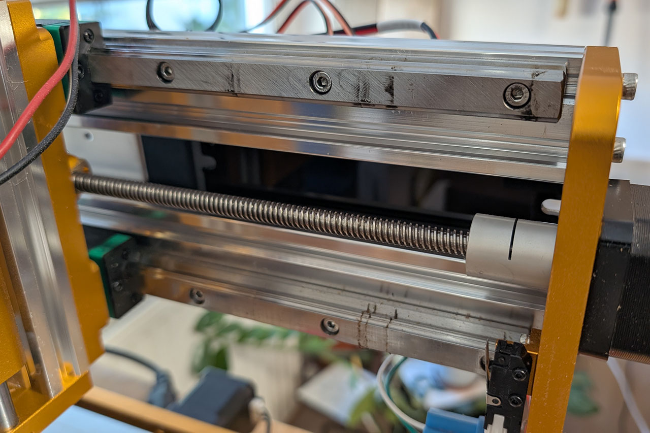
| Motion System | HGH15 linear guide on the X-axis |
| Software Compatibility | GRBL, Candle, UGS, Fusion 360, Easel, OpenBuilds Control |
| Compatible Materials | Wood, MDF, acrylic, plastic, soft metals like aluminum, copper |
| Power Supply | 24V power supply, included in the delivery |
| Net Weight | 14kg |
| Special Features | Emergency stop switch, aluminum Z-plate, Z-probe sensor, laser upgradeable |
The compact dimensions of the mill are, of course, a blessing and a curse. I don't have much space in my workshop, so a larger mill would have been problematic. On the other hand, the limited working area of 30 × 18 cm is quite restrictive in terms of workpiece size. However, I consciously accepted this compromise.
Assembly and Adjustment
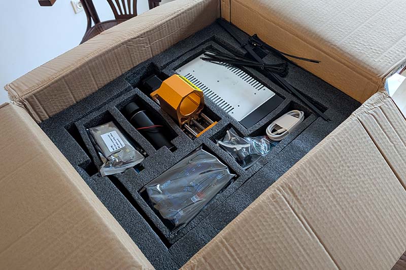
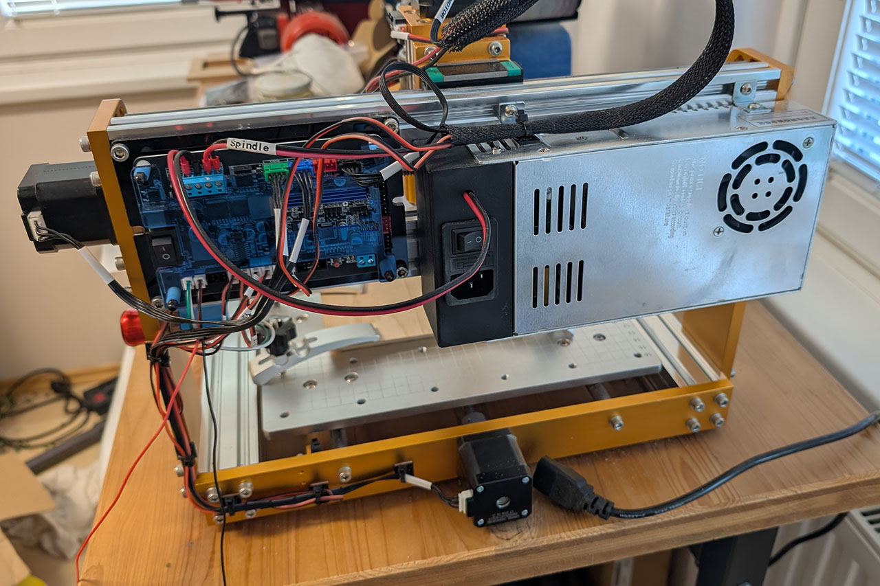
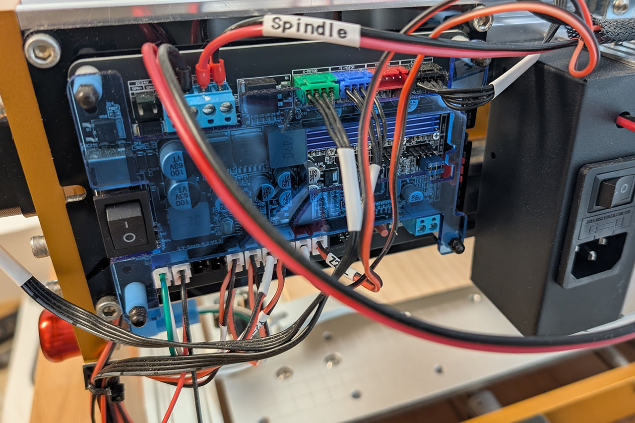
The mill is delivered as a kit, which, however, consists of only a few parts and can be easily assembled in about an hour. To do this, you simply screw the gantry with the Z and X-axis onto the platform with the Y-axis. Then, you attach the rubber feet to the bottom, insert the spindle, mount the power supply and controller, and finally connect all components with the pre-terminated cables.
With that, the mill is basically ready to use. In my case, however, I noticed that the distance between the spindle (Z-axis) and the base plate varied slightly along the X-axis, meaning it wasn't the same everywhere. The cause was a minimal strain in the frame. I therefore loosened all the screws, including the pre-assembled ones, and realigned and tightened the entire mill from scratch. Afterward, the axis was perfectly parallel to the work surface.
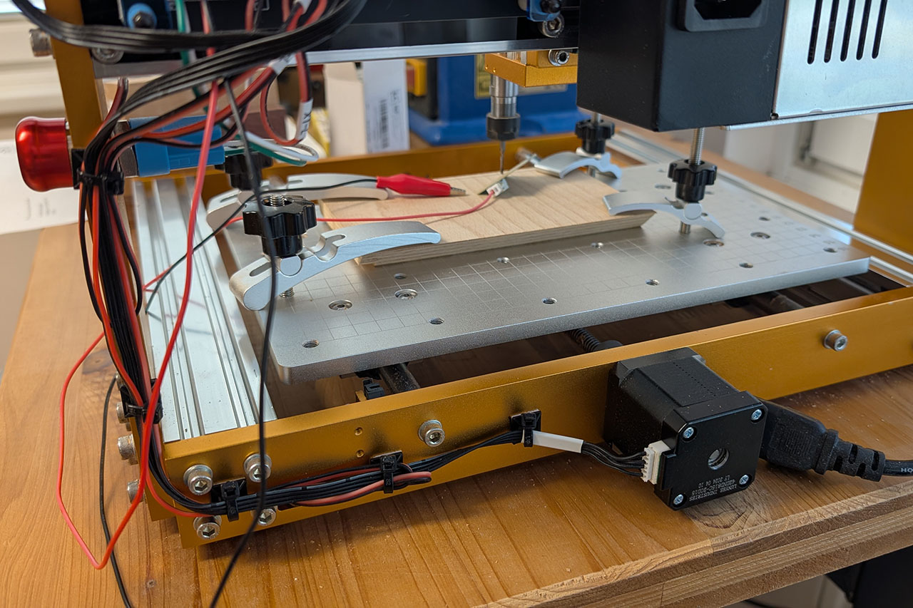
Here are some more pictures of the CNC mill:

It is highly recommended to invest some time in a precise alignment during assembly, as this initial effort will be rewarded later with clean milling results. Especially with CNC mills, the quality of the assembly often determines the reliability and accuracy of the machine later on.
Commissioning & Software: CNC Milling for Beginners
For someone like me, who has experience with 3D printing but has never worked with a CNC mill before, the question inevitably arises after assembly: Now what? How do I get my design into the mill? What software do I need? And what exactly is GRBL?
CNC Milling vs. 3D Printing – What's Different?
In 3D printing, material - typically plastic - is built up layer by layer. This is called an additive process. A CNC mill, on the other hand, works subtractively: a rotating cutting tool removes material. The workpiece, e.g., wood or aluminum, already exists and is then shaped.
What sounds simple in theory involves some important differences in practice:
- While in 3D printing the object adheres to the print bed on its own, the workpiece in CNC milling must be securely mechanically fastened.
- Instead of a nozzle with hot plastic, a high-speed end mill is used. This requires special caution. Always wear safety glasses!
- The software is also different: instead of slicer programs, you need CAM software to calculate the toolpath, and subsequently, a control program to execute the G-code.
I had already gathered some experience with 3D printing before I ventured into CNC milling. Nevertheless, getting started was surprisingly demanding. Roughing, finishing, depth of cut, feed rate, plunging. All terms that were completely new to me. Which end mill is suitable? How deep can I cut per pass? How fast can the cutter move without causing tear-out or overloading the spindle? How do I secure the workpiece safely? Which order of operations makes sense to avoid damaging anything? All of this affects the milling result – and a mistake can quickly lead to a damaged workpiece, cutter, or in the worst case, the machine itself.
In short: with a CNC mill, you need to know significantly more before you can start – but that's exactly what makes working with it so exciting and educational. Every workpiece is a small adventure.
GRBL – The "Operating System" of the Mill
The Lunyee 3018 Pro Ultra is controlled by a small microcontroller running the open-source firmware GRBL. This software is, so to speak, the "operating system" of the mill. It receives commands from the computer and uses them to control the motors of the X, Y, and Z axes, the spindle, and the limit switches.
The commands themselves consist of so-called G-code – a simple, text-based language used to tell the machine where to go and how deep to mill. A typical G-code command looks like this, for example:
G1 X10 Y20 Z-1.5 F300
This means: Move in a straight line (G1) to the coordinates X = 10, Y = 20, Z = -1.5 mm at a speed (Feed rate) of 300 mm/min. This type of G-code is not written by hand – it is generated automatically from a CAD drawing using so-called CAM software.
Besides GRBL, there are other CNC control systems like Estlcam, Mach3/Mach4, or UCCNC. These are usually more powerful, supporting more axes, automatic tool changers, or higher execution speeds, but they are often paid and sometimes significantly more complex to set up.
What Software You Need
For everything to work together, you essentially need three programs:
- A CAD program where the workpiece is designed. Here you create the desired shape, usually as a 3D model. I use Fusion 360 for this because it's free for personal use and offers a very good range of functions. Alternatively, I'd like to try FreeCAD soon, which is completely open source.
- A CAM program where you define how the workpiece is to be milled – i.e., which cutters to use, what the appropriate depth of cut is, whether to use roughing or finishing passes, what feed rate to use, etc. In the end, this generates the so-called G-code, which instructs the mill step by step. Before it can be exported, a post-processor must be selected. It converts the milling strategy into the correct format for the specific machine controller (for example, GRBL). Many programs, such as Fusion 360 or FreeCAD, combine CAD and CAM in one interface, which makes getting started much easier.
- A control program (or G-code sender) where the G-code is loaded and which communicates directly with the mill. With it, you can jog the axes, set the zero point, and start, pause, or stop the milling process. I used Candle for this myself; alternatives include UGS (Universal Gcode Sender) or OpenBuilds Control.
To demonstrate the workflow from design to the finished milled part, I have designed a simple workpiece to illustrate the steps with an example.
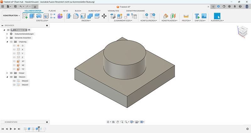
CAD – Designing the Model
The first step is to create a 3D model of the workpiece. For my example, I used Fusion 360, but of course, any other CAD program can be used. I recommend placing the bottom of the workpiece on the XY plane from the start, as this saves you from having to reorient the axes later in the CAM part.
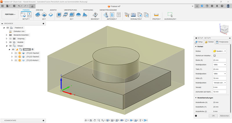
Once the model is finished, you switch to the Manufacture workspace in Fusion 360. If the model was created in another CAD program, it must be exported as a STEP file and imported into Fusion 360.
CAM – Defining the Milling Strategy
Before you can mill, a Setup must be created in the CAM environment. Here, you define, among other things, the size of the raw material (stock) you want to machine. The values in the X and Y directions are not as critical, as you will later set the zero point, which is defined as the starting position. The height, however, is very important, as this value determines how much material needs to be removed from the top. Additionally, the orientation of the part within the stock is also defined. I position my parts at the bottom of the stock. This has the advantage that later, when milling, the Z-zero can simply be set to the surface of the spoilboard. Furthermore, the origin of the coordinate system must be defined. These values will also be set on the mill later, so that the CAM model matches the real workpiece.
Before you can begin with the individual milling steps, the tools must be defined first. In this example, I am using a 2mm flat end mill that came with the Lunyee 3018 Pro Ultra. I measured the cutter with a caliper and entered the values into the setup. Besides the basic dimensions, there are countless other values, such as the cutter's material, number of flutes, etc.
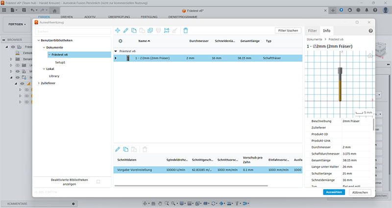
For many of these values, you probably need to have studied mechanical engineering to really understand what they mean. You might get these values from the manufacturer with professional tools, but with cheap cutters from China, that's unlikely.
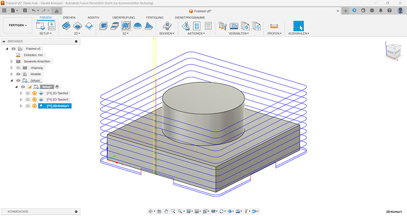
Now the individual milling operations can be created. In this example, I used 2D Pocket and 2D Contour. Instead of 2D pockets, one could also have used a 3D contour; here, you probably just have to gain experience to see which strategy works best for which material. With the 2D Contour, you can also define holding tabs, which are not milled out, so that the workpiece remains connected to the stock and doesn't move uncontrollably at the end and get damaged.
|
|
|
|
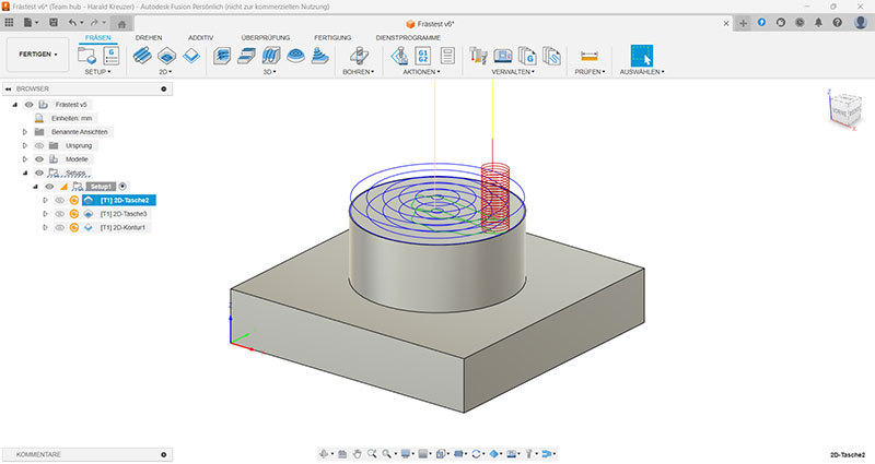
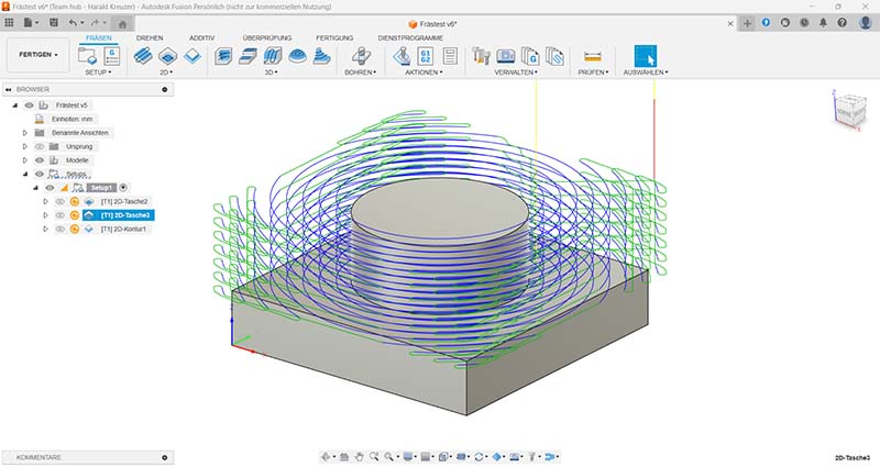
Each of these operations again offers countless parameters you can set. Most important are the cutting feed rate, i.e., how fast the cutter moves, and the maximum depth of cut, i.e., how much material is removed per pass. My values are probably a bit conservative, as the Lunyee 3018 Pro Ultra with its 500-watt spindle could certainly work faster.
You can view the milling process in the simulator at any time to judge whether the settings seem plausible.
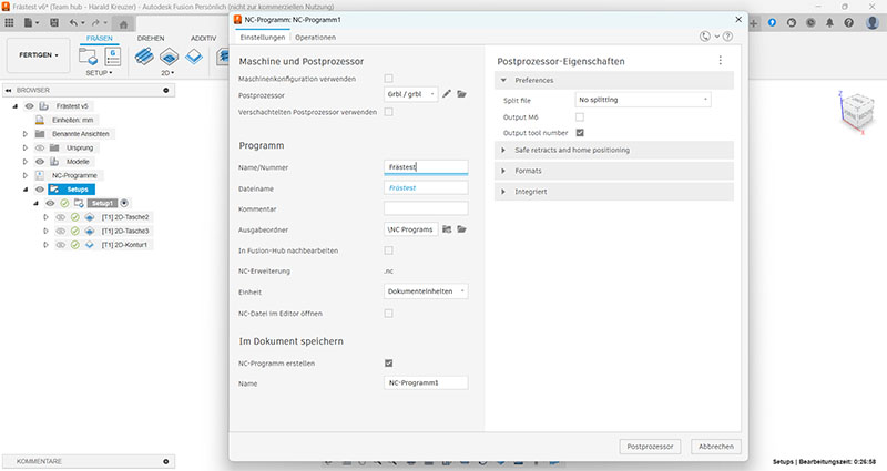
Finally, the G-code is exported. For this, an NC program is created in which the post-processor is also selected. In my case, I choose GRBL. When you click the post-process button, the G-code is written to a file. The system also checks whether the G-code can be created with these settings and post-processor.
That concludes the CAM part. As you may have noticed, I am still very uncertain about many points. On the one hand, you have to learn a lot about milling, and on the other hand, I still lack the practical experience.
Control – Operating the Mill
Finally, the actual milling takes place. As mentioned above, I use Candle for this, as this program was supplied with the Lunyee mill. First, the file with the G-code is loaded into the program. You now see the exact same toolpaths on the screen as in Fusion 360
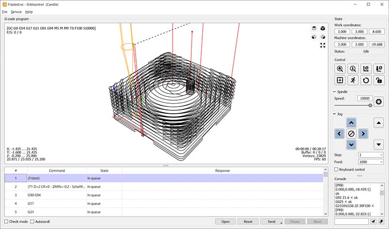
Before milling can begin, the zero points must be set exactly as they were defined in Fusion 360. For the XY-zero, the cutter is moved to the corresponding position above the stock, and the corresponding button is clicked in Candle. For the Z-zero, the supplied Z-probe is used. Candle uses a sequence of G-codes for this measurement. However, the default code for this provides very inaccurate values. On this website, I found a very good description for a better code: https://www.dragoncut.de/tipps-und-tricks/technik/z-probe-der-gcode-fuer-das-programm. The Lunyee Z-probe is 1.6 mm thick, so the Z-code looks like this:
G21G91G38.2Z-30F100;G0Z1;G38.2Z-2F10;G92Z1.6;G0Z5F10M30
Since I set the Z-zero to the bottom of the workpiece in Fusion 360, the Z-probe must also be placed directly on the spoilboard:
Now the milling can begin. To do this, you click the "Send" button in Candle, and the mill starts.
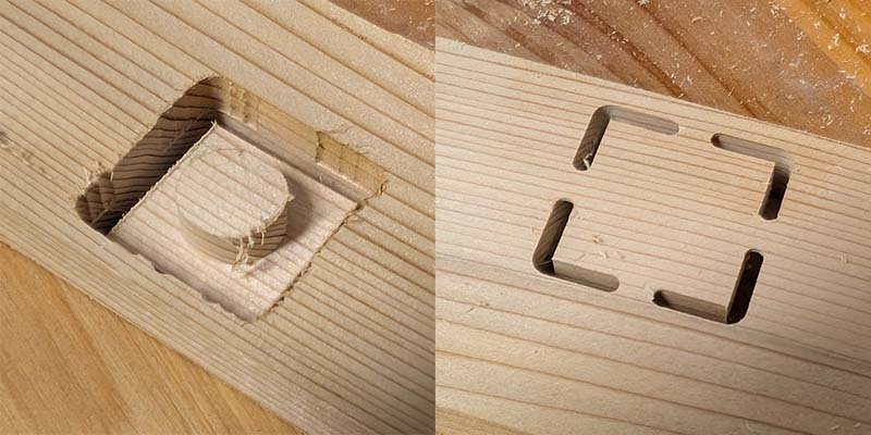
About 30 minutes later, the mill is finished. As you can see, the wood is a bit frayed, but otherwise, the result looks very good. On the right side, you can see the holding tabs that were set in Fusion 360. These tabs must now be carefully cut and then sanded down. One could also try to fix the wood with double-sided tape, but I'm not sure if that would hold securely. At least then you could save the holding tabs. The luxury option, however, would be a vacuum table, which can hold the workpiece without any additional measures.
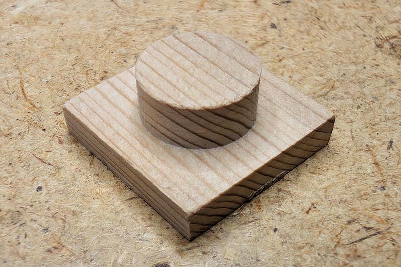
And this is what the small piece of wood looks like after sanding.
An important point, of course, is the accuracy of the mill. The square part should be 20 mm wide, the cylinder should have a diameter of 12 mm, and the height is 9 mm.
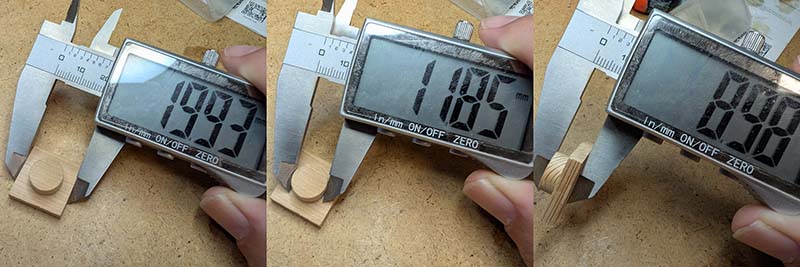
For my applications, this accuracy is perfectly sufficient. A deviation of one or two tenths of a millimeter also corresponds roughly to the specifications on the Lunyee website, where the accuracy is stated as +/- 0.1 mm.
Conclusion
My journey into the world of CNC milling was born out of a desire to overcome the limitations of my 3D printer and to finally be able to machine materials like wood with precision. The Lunyee 3018 Pro Ultra has proven to be the ideal choice for this step. For a price of around 450 euros, it offers an outstanding value for money. The sturdy metal frame, the powerful 500W spindle, and the extensive accessory package clearly set it apart from mere "toy" models and create a solid foundation for serious hobby projects.
However, it's also clear: the path from assembly to the first finished part is more demanding than with 3D printing. Getting familiar with the chain of CAD, CAM, and control software, as well as the many new technical terms, requires patience and a willingness to learn. But that's exactly what makes the process so exciting and educational.
In summary, the Lunyee 3018 Pro Ultra is a strong recommendation for all makers, hobbyists, and 3D printing enthusiasts who want to take the next step. It's not a professional device, but it is a fantastic, solid tool that throws the door wide open to new materials and projects. Anyone willing to put in the effort to learn the ropes will be rewarded with a reliable and sufficiently precise machine.