Designer clock from the 3D printer with the Raspberry Pi: The Zyklochron.
If I had known from the beginning how elaborate this project would be, I don't think I would have started it at all. Unfortunately, I can't tell you anymore how I came up with the idea. Suddenly this image of a clock was in front of my mind's eye. The beginning of a very exciting time.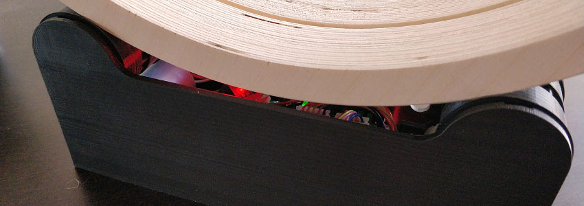
The idea
What does this picture look like? Basically very simple. There are two rings for hours and minutes, one behind the other, which are somehow moved by a mechanism with rollers. The diameter is about 30 cm and the width about 3 cm. And these rings should have no fixed connection with the drive. Probably you can't imagine much about it now, but that will become clearer in the course of the article.
So now I had a vague idea in my head, but how do you go about such a project? The longer I thought about it, the more questions came up. Where do I get the rings? The drive rollers? Which motors? How will the clock be controlled? With which mechanics? At first, this seemed pretty hopeless with my resources.
Rings
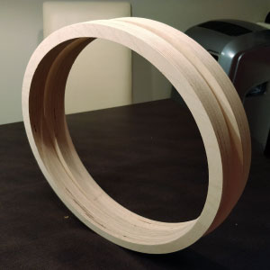
Of all the questions, the rings seemed the easiest to me. Which material should I use? I decided on wood, as that seemed the easiest to work with. In principle, however, the clock should work with any material, whether wood, aluminum, acrylic or glass. A first search for wooden rings in Google and on Amazon was sobering. Lots of jewelry or rings to craft with, but nothing that would work for my clock. In desperation, I even started looking into routers and watched dozens of videos on YouTube. After a long search, I finally came across a German company that offers components for building speakers. Among other things, also freely configurable MDF wooden rings. For a prototype, that's enough. A week later the rings were there. However, they were so roughly milled that I then had to sand them for hours.
Mechanics
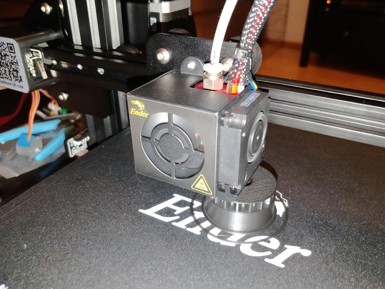
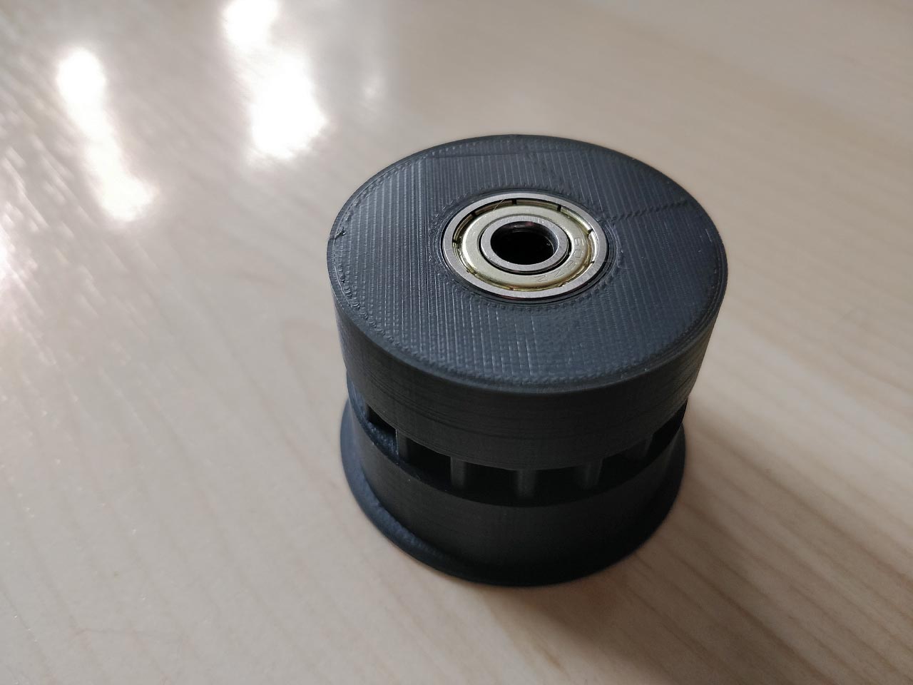
The mechanics were much more difficult. Mainly because I didn't have the slightest idea how to build it. Again, I first tried Amazon and searched for rollers. There are all kinds of transport rollers, furniture rollers and heavy-duty rollers, but how should the rings stand on them and how are they driven? The fact was, with my possibilities I could not implement that. But then I had the saving idea. Maybe it would work with a 3D printer? At that time, I knew absolutely nothing about 3D printing. But that changed quickly and soon the printer was ordered.
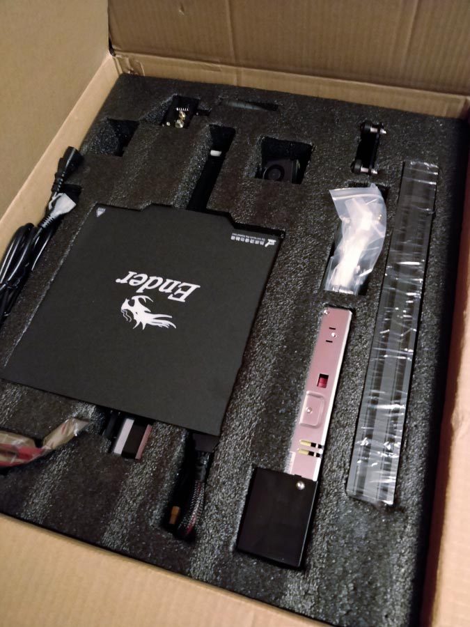
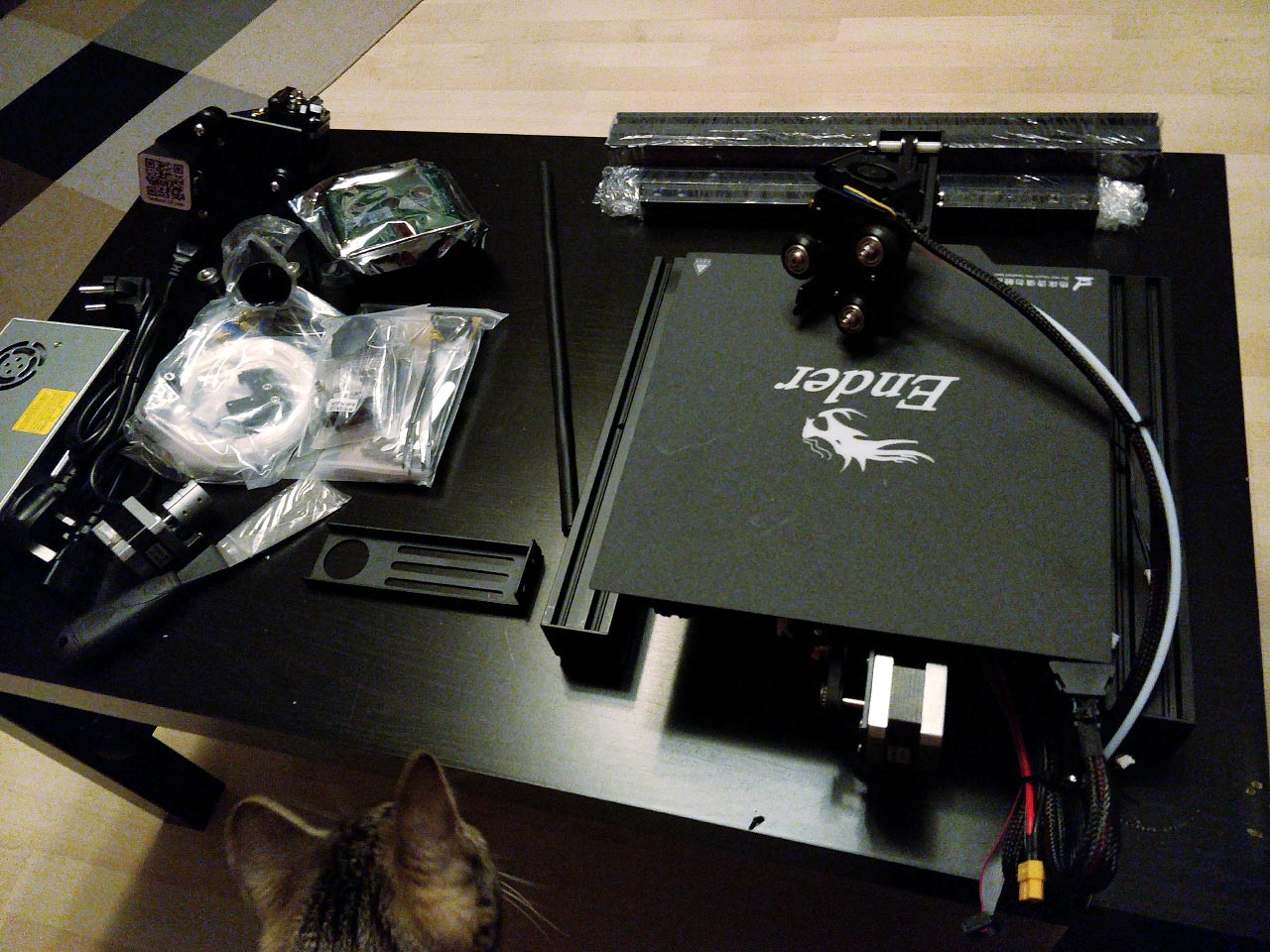
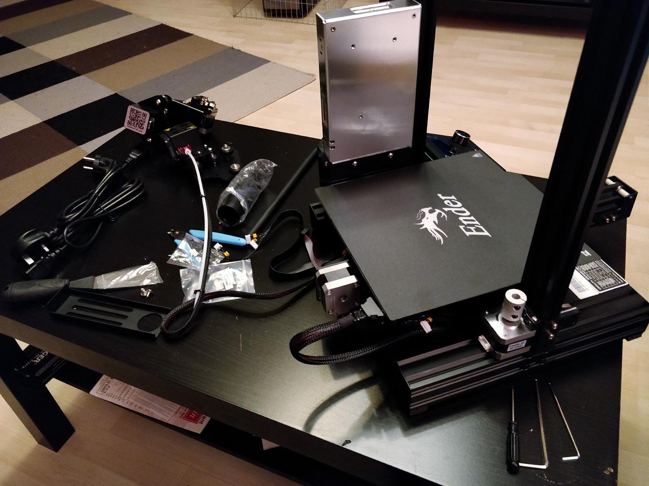
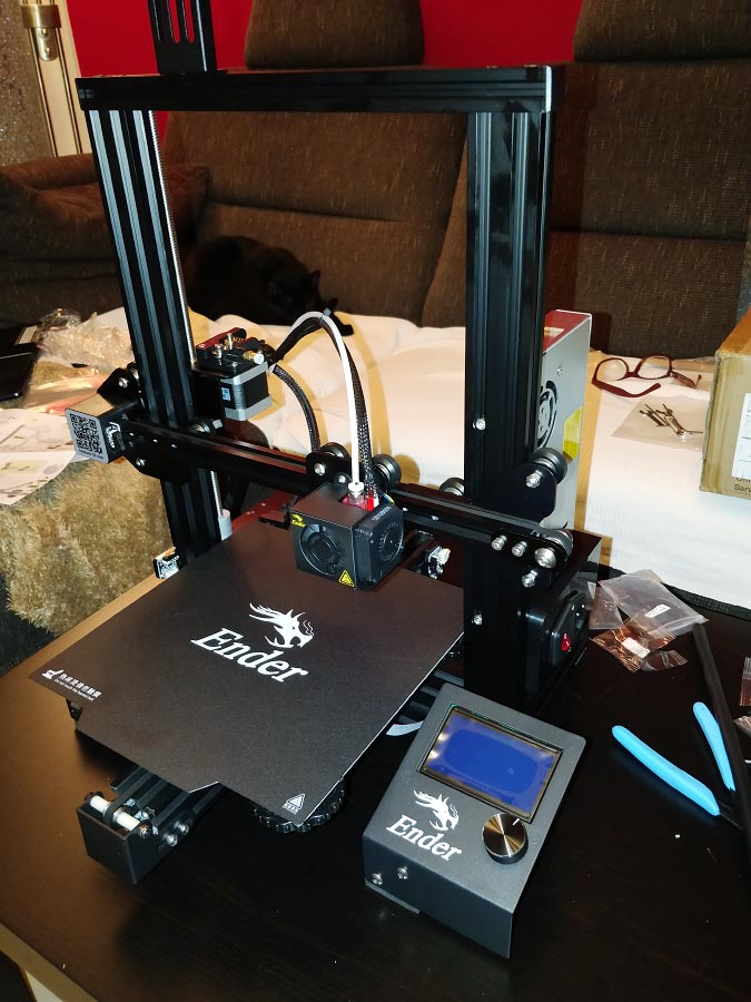
I chose the Ender 3 Pro from Creality because it was reasonably cheap and the reviews were quite positive. In two hours, the kit was built. Now I just had to design the components so that the 3D printer could print something. Again, a topic I had no idea about. How and with what do you make CAD constructions? My first bumpy attempts I made with Tinkercad and FreeCAD. But somehow I couldn't really make friends with the programs. 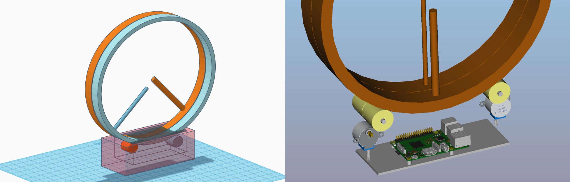
Electronics
For the control of the clock I had two options. Arduino or Raspberry Pi. In the end I decided for the Raspberry Pi, for the simple reason that it already has a clock built in while the Arduino would have needed another part. Unfortunately the Raspberry doesn't have a backup battery, but thanks to WiFi it always fetches the current time automatically at startup.
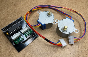
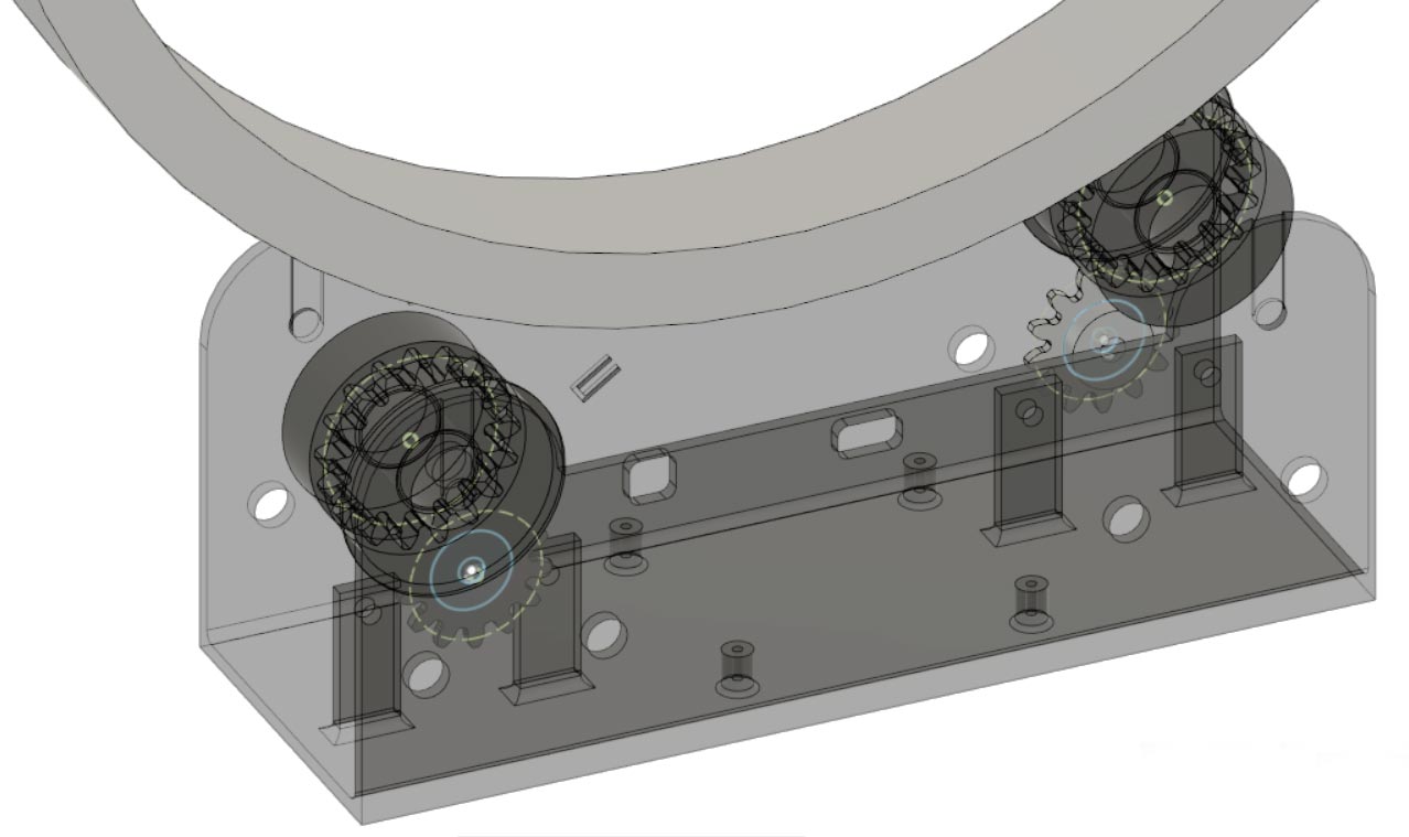
Two stepper motors are responsible for the drive. Since the motors need almost no power for the rotation of the rings, I decided to use very small models of the type 28BYJ-48. The corresponding motor controller can simply be plugged onto the Raspberry Pi. The big advantage of these motors is that they get by with the 5V from the Raspberry Pi power supply and don't need their own power supply. They also have a small gearbox built in, which is very beneficial for smooth running of the clock.
But there was one last problem to solve. How does the controller know where the hands are? The obvious solution would be a mark on the rings that can be measured with an optical sensor. However, I didn't want any lines or indentations to be seen on the rings. At some point I remembered my physics class, where we talked about Hall sensors. With these, magnetic fields can be measured and a small magnet could easily be hidden under the hand. And indeed, such sensors can be bought. A first test was very promising.
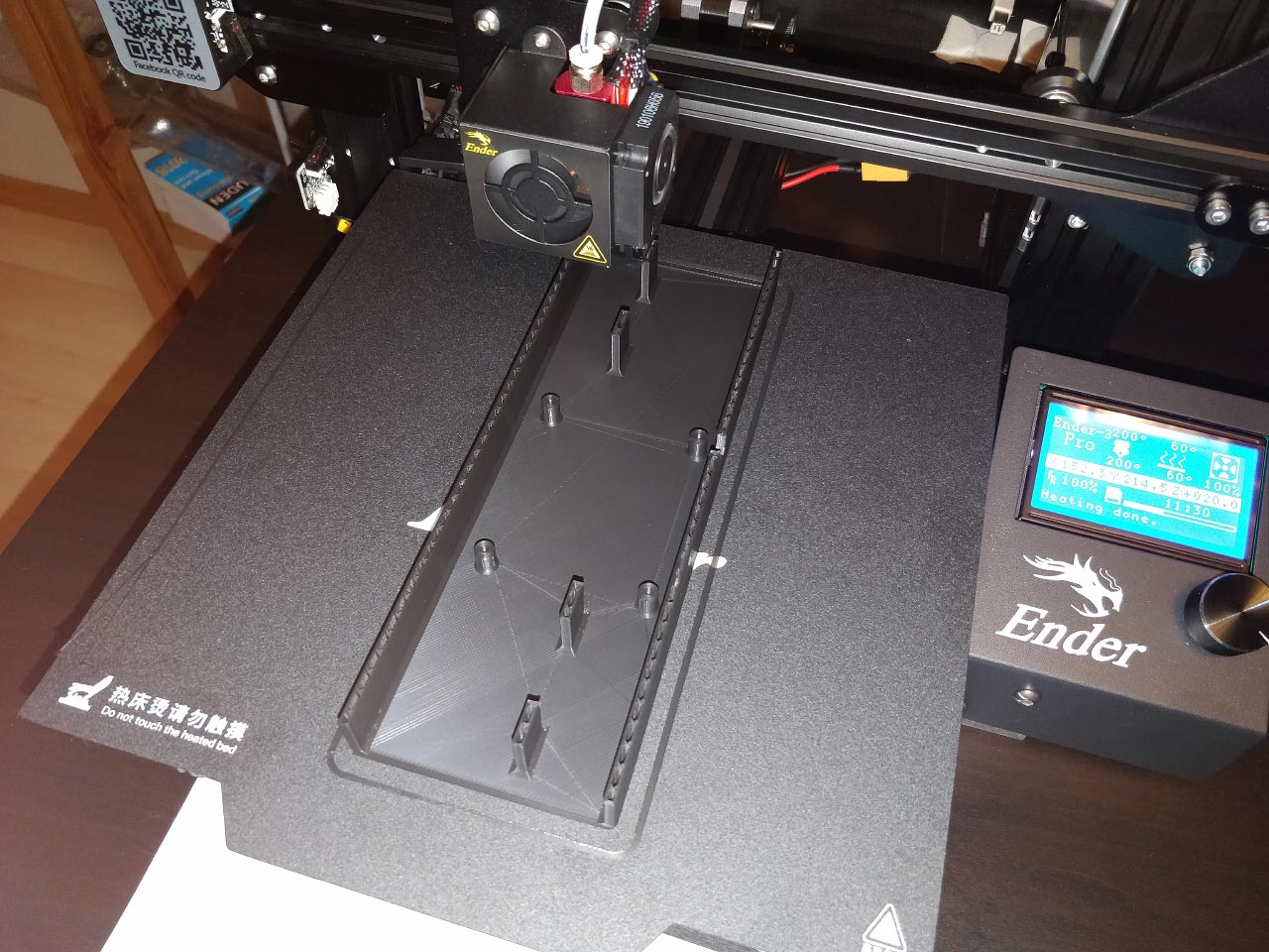
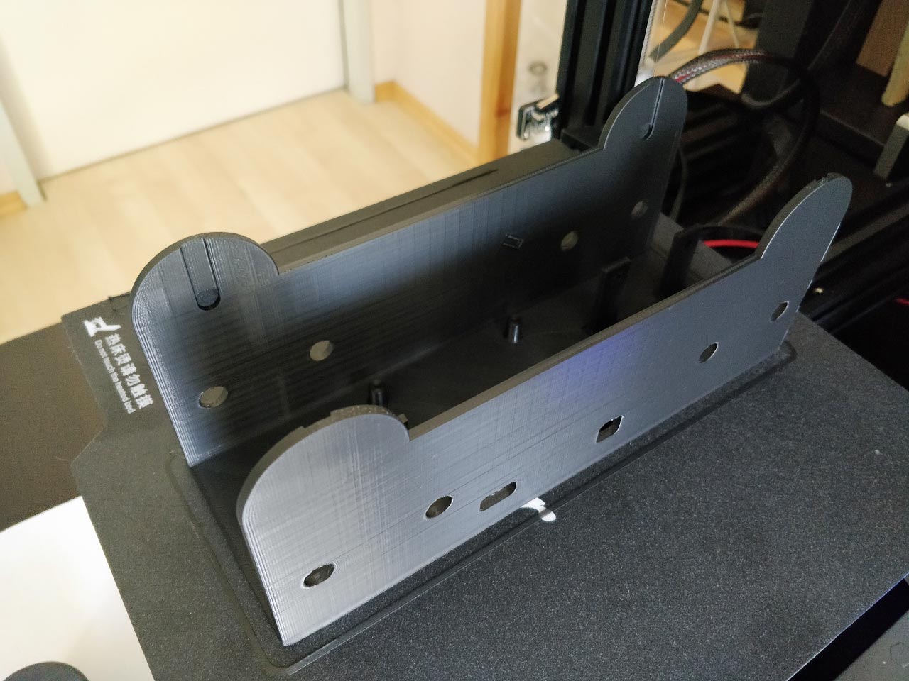
I then installed all the components, i.e. stepper motors, the Raspberry, the motor controller and the Hall sensors in the housing. This was a very exciting moment, because up to this point I didn't know if all dimensions and drill holes in my construction really fit. Fortunately I measured correctly and in the end the construction looks like this: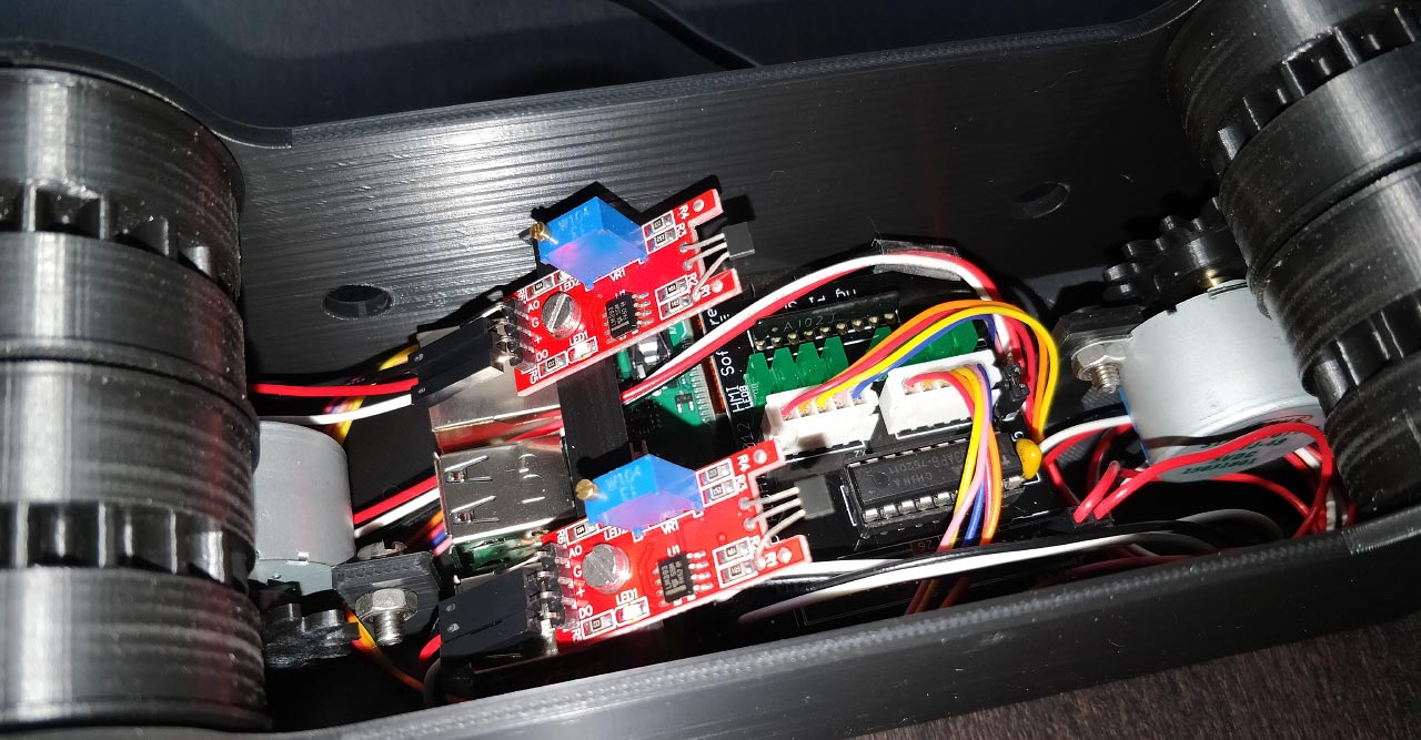
Software
The last thing left was the software. Finally something I am already familiar with. Basically, the Raspberry Pi has a wide range of programming languages that I could use to implement the software. I used Java, because on the one hand I have the most experience with it and on the other hand there is Pi4J, a very good library to access the GPIO ports of the Raspberry Pi. This library is based on WiringPi, which has to be installed on the Raspberry Pi. With this it is now quite simple to control all the hardware, such as the stepper motors:
As development environment I use the Community Edition of IntelliJ, in my opinion one of the best IDEs on the market. Additionally I recommend the plugin Embedded Linux JVM Debugger, with it you can start the program on the Raspberry Pi from IntelliJ and also debug it.
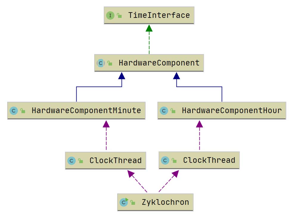
The control software consists of only a few components. For hours and minutes a thread is started, which gets the necessary information about the hardware, especially the ports. The overall structure looks like this:
At the beginning, the thread does not yet know anything about the position of the pointer or the size of the rings. Therefore, the thread starts right after the start with the search for the pointer. If this is found, the size of the ring is measured. With this information now the actual and target position of the pointers can be calculated. After each rotation, the clock is automatically readjusted so that the two values do not drift apart. Here is a short time-lapse video of what this looks like:
Although I have been working in Java development for several years now, this was my first program in which I interact with the real world. And this world is not digital, which caused me some problems in the beginning. For example, the Hall sensors don't just jump from 0 to 1, but oscillate in the transition area when the magnet comes close to the sensor. Accordingly, the software must be able to handle these situations. Also, the number of steps per revolution is not always the same, so constant adjustment is also necessary.
Name
One very last point was still open. What name should the watch have? I wrote down all the possible words I could think of on the subject. Rotor, Orbiter, Radial, Clock, Spin, Ring and many others. But all the word creations somehow already existed, no matter if Greek, Latin or English.
Then I came up with Zyklochron, based on the Greek words for circle and time. A search on Google returned.... nothing! Perfect. So now the clock had its name.
Final
So now the prototype of the clock is finished. About seven weeks have passed since the first idea. During this time, I have learned an incredible amount. Above all, I see 3D printing as a great enrichment that opens up many possibilities for future projects. I've also learned a bit about electronics. I'll certainly be working on this topic more intensively in the future.
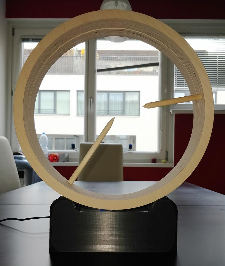
Finally, of course, the final photo of the watch should not be missing. This is how it looks in all its glory and has been running flawlessly ever since.
But there are also some questions left unanswered. I still do not know who can make me such rings from acrylic or aluminum. Especially nice would also be rings that are milled from a piece of wood. Is that possible at all? It would have to be a very hard wood that doesn't crack. Or how could I have the printed parts made without a 3D printer? With injection molding? Is that even possible for such a small number of pieces? And if so, how much does it cost? Another problem is the gears. Unfortunately, the accuracy of the 3D printer is not sufficient here. The teeth don't slide smoothly into each other, as they should, but sometimes catch a little, which makes the barrel a little rough.
As you can see, there is still some work to do and I'm sure this is not the last version of the watch. So stay tuned :)