Using Sunton/MaTouch ESP32-S3 7-inch displays with LVGL and ESP-IDF
Parallel RGB LCD displays offer a cost-effective and efficient solution for the IoT, especially in combination with the powerful ESP32-S3 microcontrollers. Their simple interface and wide availability make these displays ideal for displaying information in IoT devices. This article uses the example of the Makerfabs MaTouch and Sunton 7-inch displays to examine the functionality of the parallel RGB LCD displays and the integration with the ESP-IDF framework and the LVGL graphics library.
How parallel LCD displays work
Parallel LCD displays use a series of lines to transmit the necessary image information. The data lines play a key role in this by passing on the color information for each pixel. The displays from Makerfabs and Sunton use the RGB565 format, i.e. 5 bits for red, 6 bits for green and 5 bits for blue. A total of 16 bits are therefore required for the data.
The HSYNC and VSYNC signals mark the start of new lines or images, while the CLOCK line synchronizes the data transfer and the DATA ENABLE line indicates when the data is valid. The following diagram illustrates the time sequence:
The back porch and front porch date back to the days of CRT monitors. They were needed to synchronize and stabilize the image on the display by ensuring that the screen's electron beam was positioned correctly. These gaps are also used in modern LCD displays to stabilize the data transfer and synchronize the image structure. The correct values can be obtained either from the data sheet for the respective display or from sample programs from the manufacturer.
The displays are also equipped with a GT911 touch controller. This controller works completely independently of the display and is connected via an I²C interface. Another line controls the brightness of the display by means of pulse width modulation.
Unlike other display types, these lines are not controlled by a special LCD controller in parallel LCD displays, but by a microcontroller. This not only saves costs, but also allows greater flexibility when adapting to specific requirements. In the MaTouch and Sunton displays, the ESP32-S3 takes on this task. However, the price for this is very high. A total of 24 GPIO ports of the ESP32-S3 are required to control the displays.
ESP32-S3 and parallel LCD panels
The microcontrollers from Espressif have offered hardware support for displays since the first ESP32, but only for LCDs with their own controller, which are addressed via interfaces such as I2C or SPI. Only the ESP32-S3 also supports parallel RGB displays. The screen data is transferred from the LCD interface via DMA from the frame buffer to the display without affecting the two CPUs. This is also the reason why all larger displays with an Espressif microcontroller use the ESP32-S3.
The configuration of the RGB interface LCD driver only requires a few steps. First, all parameters such as clock source, number of frame buffers (screen memory), data width, GPIO pins or timings must be entered in the esp_lcd_rgb_panel_config_t structure. The display is then initialized with the functions esp_lcd_new_rgb_panel, esp_lcd_panel_reset and esp_lcd_panel_init.
The LCD driver offers the option of configuring the framebuffer in different ways:
- Internal memory: simplest option, but consumes the very limited internal memory.
- PSRAM: This option uses the PSRAM to relieve the internal memory. The screen data is read directly from the PSRAM via DMA. This can cause bandwidth problems, especially if the CPU and DMA access the PSRAM at the same time.
- Double PSRAM: Uses two PSRAM frame buffers to avoid tearing effects, but requires synchronization of the frame buffers.
- Bounce buffer with one PSRAM: Uses internal memory for a bounce buffer and PSRAM for a frame buffer. Offers higher pixel clock frequencies, but increases CPU load.
- Bounce buffer only: The driver does not allocate a PSRAM framebuffer. A callback function is used to fill the bounce buffer during operation.
As the displays I am using have 8 MB PSRAM, I use the variant with two PSRAM frame buffers. The function for initializing the LCD driver looks like this:
void init_lcd(esp_lcd_panel_handle_t *panel_handle) {

    ESP_LOGI(TAG, "Install RGB LCD panel driver");

    sem_vsync_end = xSemaphoreCreateBinary();
    sem_gui_ready = xSemaphoreCreateBinary();

    esp_lcd_rgb_panel_config_t panel_config = {
        .data_width = 16, // RGB565 in parallel mode, thus 16bit in width
        .psram_trans_align = 64,
        .num_fbs = 2,
        .clk_src = LCD_CLK_SRC_DEFAULT,
        .disp_gpio_num = PIN_NUM_DISP_EN,
        .pclk_gpio_num = PIN_NUM_PCLK,
        .vsync_gpio_num = PIN_NUM_VSYNC,
        .hsync_gpio_num = PIN_NUM_HSYNC,
        .de_gpio_num = PIN_NUM_DE,
        .data_gpio_nums = {
            PIN_NUM_DATA0,
            PIN_NUM_DATA1,
            PIN_NUM_DATA2,
            PIN_NUM_DATA3,
            PIN_NUM_DATA4,
            PIN_NUM_DATA5,
            PIN_NUM_DATA6,
            PIN_NUM_DATA7,
            PIN_NUM_DATA8,
            PIN_NUM_DATA9,
            PIN_NUM_DATA10,
            PIN_NUM_DATA11,
            PIN_NUM_DATA12,
            PIN_NUM_DATA13,
            PIN_NUM_DATA14,
            PIN_NUM_DATA15,
        },
        .timings = {
            .pclk_hz = LCD_PIXEL_CLOCK_HZ,
            .h_res = LCD_H_RES,
            .v_res = LCD_V_RES,
            .hsync_back_porch = HSYNC_BACK_PORCH,
            .hsync_front_porch = HSYNC_FRONT_PORCH,
            .hsync_pulse_width = HSYNC_PULSE_WIDTH,
            .vsync_back_porch = VSYNC_BACK_PORCH,
            .vsync_front_porch = VSYNC_FRONT_PORCH,
            .vsync_pulse_width = VSYNC_PULSE_WIDTH,
        },
        .flags.fb_in_psram = true, // allocate frame buffer in PSRAM
    };
    ESP_LOGI(TAG, "Create RGB LCD panel");
    esp_lcd_new_rgb_panel(&panel_config, panel_handle);

    ESP_LOGI(TAG, "Register event callbacks");
    esp_lcd_rgb_panel_event_callbacks_t cbs = {
        .on_vsync = on_vsync_event,
    };
    esp_lcd_rgb_panel_register_event_callbacks(*panel_handle, &cbs, NULL);


    ESP_LOGI(TAG, "Initialize RGB LCD panel");
    esp_lcd_panel_reset(*panel_handle);
    esp_lcd_panel_init(*panel_handle);
}
The constants are defined in separate header files, with a separate header file for the Sunton display and the two MaTouch displays.
A VSYNC callback is also defined in this function. This callback is called with every VSYNC signal, i.e. exactly when a new image is drawn:
static bool on_vsync_event(esp_lcd_panel_handle_t panel, const esp_lcd_rgb_panel_event_data_t *event_data, void *user_data)
{
    BaseType_t high_task_awoken = pdFALSE;

    // Wait until LVGL has finished
    if (xSemaphoreTakeFromISR(sem_gui_ready, &high_task_awoken) == pdTRUE) {
        // Indicate that the VSYNC event has ended, and it's safe to proceed with flushing the buffer.
        xSemaphoreGiveFromISR(sem_vsync_end, &high_task_awoken);
    }

    return high_task_awoken == pdTRUE;
}
I will explain the background to this function and the meaning of the semaphore below.
GT911 Touch Controller
In this example, I am using the GT911 component from Espressif. However, the MaTouch display with the 1024x600 pixel resolution had the problem that the provided touch coordinates did not match the display. Vertically, the values ranged from 0 to 768. The Makerfabs Wiki recommends correcting the coordinates with a map function. In my opinion, however, it is better to configure the GT911 directly in the correct way. Since the Espressif driver does not offer a function for writing the corresponding registers, I have implemented a new function for this purpose. This writes the correct values to registers 0x8048 and 0x804A:
static esp_err_t touch_gt911_write_resolution(esp_lcd_touch_handle_t tp, uint16_t x_max, uint16_t y_max)
{
    esp_err_t err;

    uint8_t len = 0x8100 - ESP_LCD_TOUCH_GT911_CONFIG_REG + 1;
    uint8_t config[len];

    ESP_LOGI(TAG, "Write resolution");

    ESP_RETURN_ON_ERROR(touch_gt911_i2c_read(tp, ESP_LCD_TOUCH_GT911_CONFIG_REG, (uint8_t *)&config[0], len), TAG, "GT911 read error!");

    config[1] = (x_max & 0xff);
    config[2] = (x_max >> 8);
    config[3] = (y_max & 0xff);
    config[4] = (y_max >> 8);

    uint8_t checksum = calcChecksum(config, len - 2);
    ESP_LOGI(TAG, "Checksum:%u", checksum);

    config[len - 2] = calcChecksum(config, len - 2);
    config[len - 1] = 1;

    err = esp_lcd_panel_io_tx_param(tp->io, ESP_LCD_TOUCH_GT911_MAX_X, (uint8_t *)&config[1], 2);
    ESP_RETURN_ON_ERROR(err, TAG, "I2C write error!");
    err = esp_lcd_panel_io_tx_param(tp->io, ESP_LCD_TOUCH_GT911_MAX_Y, (uint8_t *)&config[3], 2);
    ESP_RETURN_ON_ERROR(err, TAG, "I2C write error!");

    err = esp_lcd_panel_io_tx_param(tp->io, ESP_LCD_TOUCH_GT911_CHKSUM, (uint8_t *)&config[len - 2], 1);
    ESP_RETURN_ON_ERROR(err, TAG, "I2C write error!");
    err = esp_lcd_panel_io_tx_param(tp->io, ESP_LCD_TOUCH_GT911_FRESH, (uint8_t *)&config[len - 1], 1);
    ESP_RETURN_ON_ERROR(err, TAG, "I2C write error!");

    return ESP_OK;
}
This function only needs to be called once in esp_lcd_touch_new_i2c_gt911. The touch coordinates then match the display coordinates exactly.
Another function is responsible for reading out the touch coordinates:
static void touchpad_read(lv_indev_drv_t *indev_driver, lv_indev_data_t *data)
{

    esp_lcd_touch_handle_t touch_handle = (esp_lcd_touch_handle_t)indev_driver->user_data;

    uint16_t touchpad_x;
    uint16_t touchpad_y;
    uint16_t touch_strength;
    uint8_t touch_cnt = 0;

    data->state = LV_INDEV_STATE_REL;

    esp_lcd_touch_read_data(touch_handle);
    bool touchpad_pressed = esp_lcd_touch_get_coordinates(touch_handle, &touchpad_x, &touchpad_y, &touch_strength, &touch_cnt, 1);
    if (touchpad_pressed) {

        data->state = LV_INDEV_STATE_PR;

        /*Set the coordinates*/
        data->point.x = touchpad_x;
        data->point.y = touchpad_y;
    }
}
This function is assigned as a callback function for the touch driver during LVGL initialization.
LVGL with ESP-IDF
Most LVGL examples for the ESP32 also integrate a graphics library such as LovyanGFX or Arduino_GFX. However, these are not absolutely necessary. LVGL can also be used directly with the ESP-IDF framework.
To do this, the LVGL graphics library is first initialized with the lv_init function. The two frame buffers generated by the ESP-IDF framework are then assigned using the functions esp_lcd_rgb_panel_get_frame_buffer and lv_disp_draw_buf_init. Then only the display driver and the touch driver need to be initialized. This function looks like this:
void init_lvgl(esp_lcd_panel_handle_t panel_handle, esp_lcd_touch_handle_t touch_handle) {

    ESP_LOGI(TAG, "Initialize LVGL library");

    lvgl_mux = xSemaphoreCreateRecursiveMutex();

    static lv_disp_draw_buf_t disp_buf; // contains internal graphic buffer(s) called draw buffer(s)
    static lv_disp_drv_t disp_drv;      // contains callback functions

    lv_init();

    ESP_LOGI(TAG, "Use PSRAM framebuffers");
    void *buf1 = NULL;
    void *buf2 = NULL;
    esp_lcd_rgb_panel_get_frame_buffer(panel_handle, 2, &buf1, &buf2);
    lv_disp_draw_buf_init(&disp_buf, buf1, buf2, LCD_H_RES * LCD_V_RES);


    ESP_LOGI(TAG, "Register display driver to LVGL");
    lv_disp_drv_init(&disp_drv);
    disp_drv.hor_res = LCD_H_RES;
    disp_drv.ver_res = LCD_V_RES;
    disp_drv.flush_cb = lvgl_flush_cb;
    disp_drv.draw_buf = &disp_buf;
    disp_drv.user_data = panel_handle;
    disp_drv.full_refresh = true;
    lv_disp_drv_register(&disp_drv);

    ESP_LOGI(TAG, "Register input device driver to LVGL");
    static lv_indev_drv_t indev_drv;
    lv_indev_drv_init(&indev_drv);
    indev_drv.type = LV_INDEV_TYPE_POINTER;
    indev_drv.read_cb = touchpad_read;
    indev_drv.user_data = touch_handle;
    lv_indev_drv_register(&indev_drv);

    ESP_LOGI(TAG, "Start lv_timer_handler task");

    xTaskCreate(lvgl_port_task, "LVGL", LVGL_TASK_STACK_SIZE, NULL, LVGL_TASK_PRIORITY, NULL);
}
The setting disp_drv.full_refresh = true; ensures that LVGL always writes the entire screen content to the frame buffer. This means that the flush_cb callback only requires switching between the two frame buffers.
The flush_cb callback looks like this:
static void lvgl_flush_cb(lv_disp_drv_t *drv, const lv_area_t *area, lv_color_t *color_map)
{
    esp_lcd_panel_handle_t panel_handle = (esp_lcd_panel_handle_t) drv->user_data;

    int offsetx1 = area->x1;
    int offsetx2 = area->x2;
    int offsety1 = area->y1;
    int offsety2 = area->y2;

    // LVGL has finished
    xSemaphoreGive(sem_gui_ready);
    // Now wait for the VSYNC event.
    xSemaphoreTake(sem_vsync_end, portMAX_DELAY);

    // pass the draw buffer to the driver
    esp_lcd_panel_draw_bitmap(panel_handle, offsetx1, offsety1, offsetx2 + 1, offsety2 + 1, color_map);
    lv_disp_flush_ready(drv);
}
The two semaphores sem_gui_ready and sem_vsync_end, which were already used in the VSYNC callback, are used here again. These two semaphores ensure that the data is always sent to the display exactly at the beginning of the screen refresh. This prevents so-called tearing effects, where parts of several frames are visible at the same time while the display is being updated.
A further semaphore is required as LVGL is not thread-safe. This means that only one process may call LVGL functions at a time. The only exceptions are events and timers. Otherwise, LVGL calls must always be secured with xSemaphoreTakeRecursive and xSemaphoreGiveRecursive.
Control screen brightness
The screen brightness of these displays must also be controlled by the microcontroller using pulse width modulation. The LED control (LEDC) of the ESP32-S3 is used for this, which is configured this way:
void init_backlight(void) {
    ledc_timer_config_t ledc_timer = {
        .duty_resolution = PWM_RESOLUTION,
        .freq_hz = PWM_FREQ,
        .speed_mode = LEDC_LOW_SPEED_MODE,
        .timer_num = LEDC_TIMER,
        .clk_cfg = LEDC_AUTO_CLK
    };
    ledc_channel_config_t ledc_channel = {
        .channel = LEDC_CHANNEL,
        .duty = 0,
        .hpoint = 0,
        .intr_type = LEDC_INTR_DISABLE,
        .gpio_num = LEDC_PIN_NUM_BK_LIGHT,
        .speed_mode = LEDC_LOW_SPEED_MODE,
        .timer_sel = LEDC_TIMER,
        .flags.output_invert = LEDC_OUTPUT_INVERT
    };

    ESP_LOGI(TAG, "Initializing LCD backlight");
    ledc_timer_config(&ledc_timer);
    ledc_channel_config(&ledc_channel);
}
The brightness can be adjusted with this function, which only changes the duty cycle of the LEDC timer:
void set_backlight_brightness(uint8_t brightness) {
    ESP_LOGI(TAG, "Setting LCD backlight brightness to %d", brightness);

    ledc_set_duty(LEDC_LOW_SPEED_MODE, LEDC_CHANNEL, brightness);
    ledc_update_duty(LEDC_LOW_SPEED_MODE, LEDC_CHANNEL);
}
The PWM frequency is 200 Hz. The MaTouch board uses the RY3730 step-up converter for the backlight. The specifications in the data sheet for the frequency are somewhat strange here:
I have the feeling that something has been mixed up here and the range should rather be between 200 Hz and 1 kHz. But I'm definitely on the safe side with 200 Hz.
Demo project
To demonstrate how all the components work together, I have developed a small application. The code is developed in Visual Studio Code with the PlatformIO plugin. Before starting the project, it is necessary to create a configuration file for the MaTouch display with the following content:
{
  "build": {
    "arduino": {
      "ldscript": "esp32s3_out.ld",
      "partitions": "default_16MB.csv",
      "memory_type": "qio_opi"
    },
    "core": "esp32",
    "extra_flags": [
      "-DARDUINO_ESP32S3_DEV",
      "-DBOARD_HAS_PSRAM",
      "-DARDUINO_USB_MODE=1",
      "-DARDUINO_RUNNING_CORE=1",
      "-DARDUINO_EVENT_RUNNING_CORE=1",
      "-DARDUINO_USB_CDC_ON_BOOT=0"
    ],
    "f_cpu": "240000000L",
    "f_flash": "80000000L",
    "flash_mode": "qio",
    "hwids": [
      [
        "0x303A",
        "0x1001"
      ]
    ],
    "mcu": "esp32s3",
    "variant": "esp32s3"
  },
  "connectivity": [
    "wifi"
  ],
  "debug": {
    "openocd_target": "esp32s3.cfg"
  },
  "frameworks": [
    "arduino",
    "espidf"
  ],
  "name": "MaTouch ESP32-S3 7 Inch",
  "upload": {
    "flash_size": "16MB",
    "maximum_ram_size": 327680,
    "maximum_size": 16777216,
    "use_1200bps_touch": true,
    "wait_for_upload_port": true,
    "require_upload_port": true,
    "speed": 460800
  },
  "url": "https://www.makerfabs.com/esp32-s3-parallel-tft-with-touch-7-inch.html",
  "vendor": "Makerfabs"
}
This file is saved under the name matouch_s3.json in the local user directory in the .platformio\platforms\espressif32\boards\ directory. The content is basically the same as in the article about the Sunton display.
For the demo, I created a minimalist user interface with SquareLine Studio. With a slider you can change the brightness of the display and in the background a task counts up a counter. When the application starts correctly, the screen should look something like this:
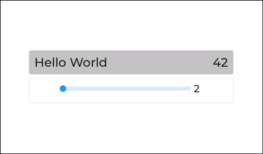
Two common scenarios are included in this demo, namely changing the GUI from a task and reacting to LVGL events and displaying them accordingly in the GUI. The structure of the project is as follows::
CMakeLists.txt
platformio.ini                           Configuration of the project
sdkconfig.defaults                       Special ESP-IDF settings
components
components\esp_lcd_touch                 General touch driver code
components\esp_lcd_touch_gt911           Customized GT911 driver
src
src\CMakeLists.txt
src\main.c                               Main program
src\lv_conf.h                            LVGL configuration
src\display
src\display\esp32_s3.c                   Display and LVGL initialization
src\display\esp32_s3.h
src\display\matouch_7inch_1024x600.h     Header file for MaTouch IPS 1024x600 pixels
src\display\matouch_7inch_800x480.h      Header File for MaTouch TN 800xs480 Pixel
src\display\sunton_7inch_800x480.h       Header File for Sunton TN 800x480 Pixel
src\gui
src\gui\gui.c                            Functions for changes in the GUI
src\gui\gui.h
src\task
src\task\counter_task.c                  Simple task with a counter
src\task\counter_task.h
src\ui                                   This folder contains the Squareline Studio Export
The code of the demo application is available on GitHub. You can find the Squareline Studio project here. If you have any questions/suggestions/improvements, feel free to leave me a message.