ESP32 library for Trinamic TMC2208 stepper motor driver
Actually, it was not intended to write a separate library for the TMC2208. The plan was to replace the previous stepper motor driver with a TMC2208 driver and then operate it in legacy mode. But then it turned out very differently...
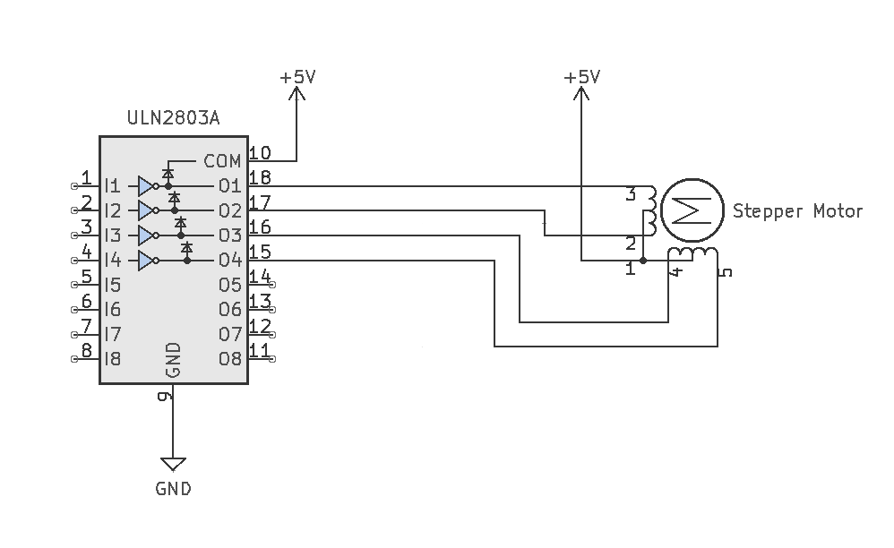
The previous stepper motor driver for the Zyklochron has a very simple structure. A ULN2803A NPN Darlington transistor array drives the stepper motor's strands directly, but this allows for half-stepping at best. This is not noticeable with the 28BYJ-48 stepper motors, since the motor has a gearbox with a gear ratio of approx. 1:64. Nevertheless, the stepper motors are quite loud, which can be very annoying, especially with a clock. When researching a better solution, I came across the TMC2208 from Trinamic. These stepper motor drivers are a kind of reference when it comes to volume. In addition to the volume, the driver has a second major advantage. According to the data sheet, it already works from a voltage of 4.75 volts. This is important because the clock is powered by a USB port.
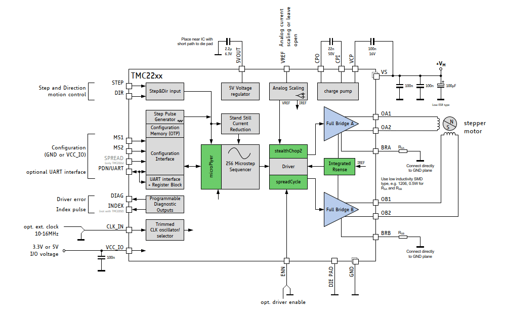
A comparison of the structure of the two drivers shows at first glance that the TMC2208 is in a completely different league:
|
ULN2803 |
TMC2208 |
|
|
|
In a first test setup, the stepper motors ran wonderfully quietly. Convinced that the circuit worked, I immediately ordered a circuit board and two weeks later installed it in the case. But then the rude awakening came. The clock was far from silent. The noise is difficult to describe, a mixture of whooshing and whistling. And it only occurred when both motors were running and was louder the slower the stepper motors were turning. Interestingly, the volume fluctuated over time. My suspicion is that some resonances are occurring here, and since the driver is constantly adjusting its parameters, this effect varies in intensity.
UART interface
Beside the legacy mode the TMC2208 supports the OTP (one-time program) mode, which I don't describe here, and the UART mode. This makes it possible to adjust many parameters of the TMC2208.
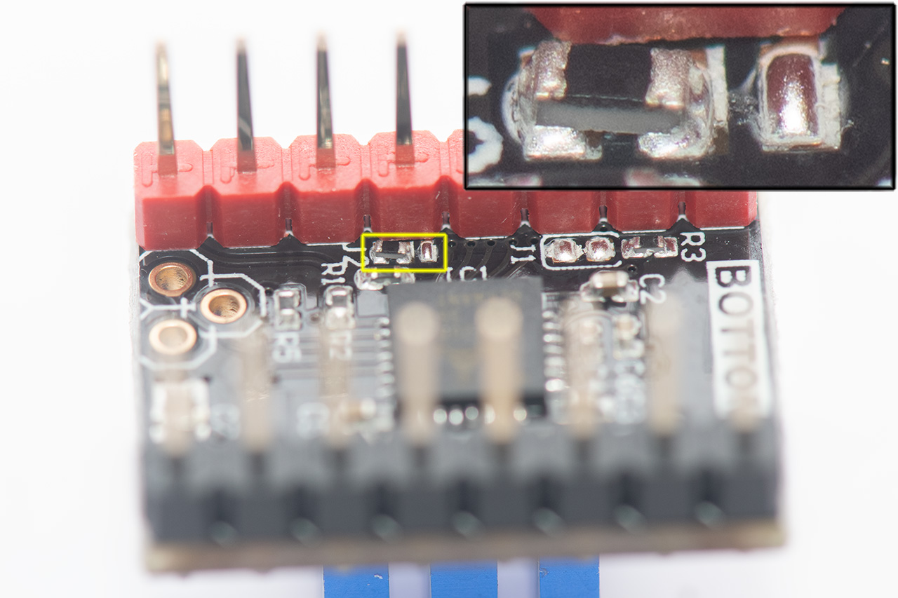
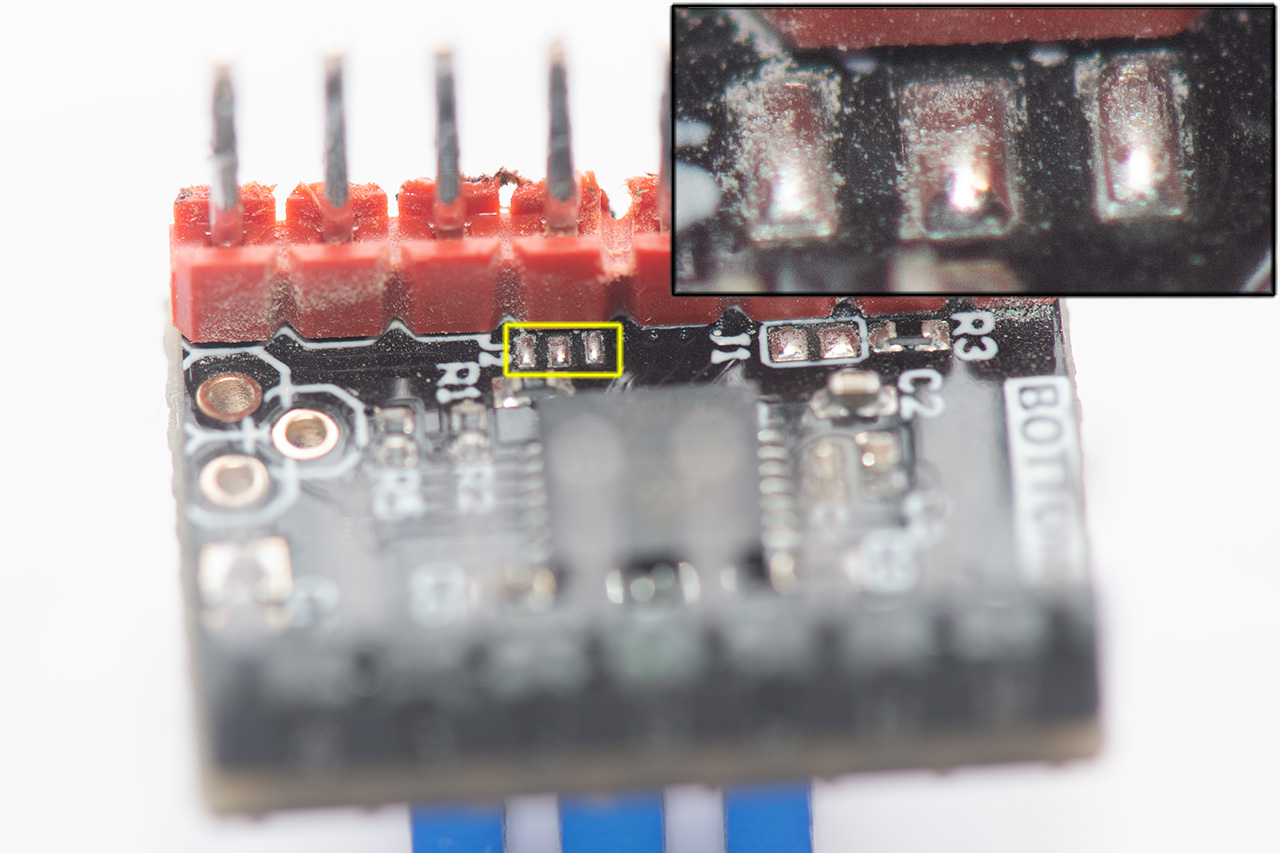
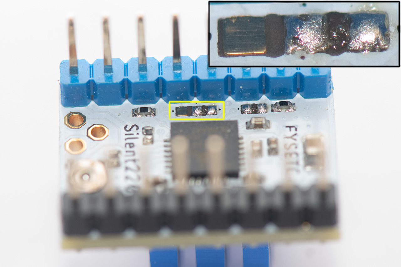
Basically every TMC2208 module supports the UART mode, but it may be necessary to close a solder bridge first, so that the pin of the module is connected to the UART interface of the chip. The easiest thing to do is to buy a module right away that already has this connection on it. Here are three examples, of which the first module from BIGTREETECH with the designation TMC2208 V3.0-UART already has the solder bridge closed.
The TMC2208 can be controlled by any microcontroller via the UART interface. It is a one-wire bus, which means that the transmit and receive lines share one wire. To connect the TMC2208 to the ESP32, the RX pin is directly connected to the UART pin of the driver and the TX pin is connected to the UART pin via a 1k resistor. The whole circuit looks like this:
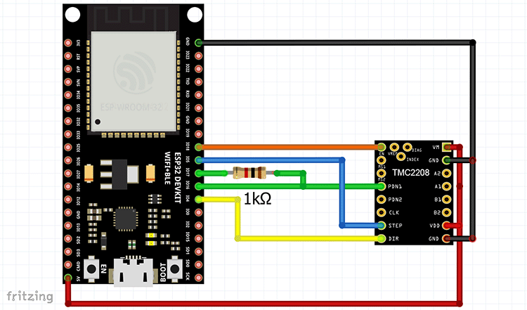
The enable line could be saved, because the TMC2208 can be enabled/disabled via the UART protocol. But since the ESP32 has enough IO pins, I have also provided this possibility. The VM connector would normally be connected to a separate power supply for the stepper motor. But since I want to supply the whole electronics exclusively over the USB port with power, I have connected the port directly to the rest of the power supply.
UART communication
How does the ESP32 microcontroller communicate with the stepper motor driver? So-called datagrams are used for this purpose, with which the registers of the TCM2208 can be read or written, whereby some registers can only be read or written. The following table gives an overview of the available registers:
| Register | Address | Read/Write | Description |
|---|---|---|---|
| GCONF | 0x00 | R/W | Global configuration flags |
| GSTAT | 0x01 | R/W (W clears) | Global status flags |
| IFCNT | 0x02 | R | Counter for write access |
| SLAVECONF | 0x03 | W | Delay for read access |
| OTP_PROG | 0x04 | W | Write access programs OTP memory |
| OTP_READ | 0x05 | R | Access to OTP memory |
| IOIN | 0x06 | R | Reads the state of all input pins |
| FACTORY_CONF | 0x07 | R/W | FCLKTRIM and OTTRIM defaults |
| IHOLD_IRUN | 0x10 | W | Driver current control |
| TPOWERDOWN | 0x11 | W | Delay time to motor current power down |
| TSTEP | 0x12 | R | Actual measured time between two microsteps |
| TPWMTHRS | 0x13 | W | Upper velocity for StealthChop voltage mode |
| VACTUAL | 0x22 | W | Moving the motor by UART control. |
| MSCNT | 0x6A | R | Microstep counter |
| MSCURACT | 0x6B | R | Actual microstep current |
| CHOPCONF | 0x6C | R/W | Chopper and driver configuration |
| DRV_STATUS | 0x6F | R | Driver status flags and current level read |
| PWMCONF | 0x70 | R/W | StealthChop PWM chopper configuration |
| PWM_SCALE | 0x71 | R | Results of StealthChop amplitude regulator |
| PWM_AUTO | 0x72 | R | Generated values for PWM_GRAD/PWM_OFS |
A detailed description of all registers and much more information can be found in the data sheet of the TMC2208.
The structure of the datagrams for write and read accesses is similar. Each datagram starts with four bits for synchronization. This allows the TMC2208 to automatically adjust to the baud rate used. At the end of each datagram is a checksum to ensure the correctness of the data.
The datagram for write access has the following structure:
| UART write access datagram structure | |||||||||||||||||||
| sync + reserved | 8 bit address | 7 bit register and write bit | 32 bit data | CRC | |||||||||||||||
| 1 | 0 | 1 | 0 | don’t cares but included in CRC | always 0x00 | address | 1 | data bytes 3, 2, 1, 0 |
checksum | ||||||||||
| 0 | 1 | 2 | 3 | 4 | 5 | 6 | 7 | 8 | ... | 15 | 16 | ... | 23 | 24 | ... | 55 | 56 | ... | 63 |
It is important that the bit after the address of the register is set to one. With each successful write access a counter is incremented. This makes it possible to check whether the data has really been written.
Read access requires two datagrams. First, the TMC2208 is informed by a write access which register you want to read. This datagram looks like this:
| UART read access request datagram structure | ||||||||||||||||
| sync + reserved | 8 bit address | 7 bit register and read bit | CRC | |||||||||||||
| 1 | 0 | 1 | 0 | don’t cares but included in CRC | always 0x00 | address | 0 | checksum | ||||||||
| 0 | 1 | 2 | 3 | 4 | 5 | 6 | 7 | 8 | ... | 15 | 16 | ... | 23 | 24 | ... | 31 |
As described above there is only one signal line for reading and writing. Therefore the TMC2208 does not send the response immediately, but waits a certain time, which can be configured by the SLAVECONF register. Default value is the time needed by 8 bits at the current baud rate. The datagram with the response is almost identical to the datagram for the write access:
| UART read access reply datagram structure | |||||||||||||||||||
| sync + reserved | 8 bit address | 7 bit register and read bit | 32 bit data | CRC | |||||||||||||||
| 1 | 0 | 1 | 0 | don’t cares but included in CRC | always 0xFF | address | 0 | data bytes 3, 2, 1, 0 |
checksum | ||||||||||
| 0 | 1 | 2 | 3 | 4 | 5 | 6 | 7 | 8 | ... | 15 | 16 | ... | 23 | 24 | ... | 55 | 56 | ... | 63 |
The structure of the datagrams and the communication with the stepper motor driver is the same for all members of the TMC22xx family with UART interface. They differ only by their functions and thus number and content of the registers.
ESP32 component
The ESP32 has three UART controllers that can be used to control the TMC2208. This allows a maximum of three stepper motors to be configured independently. The library is written in C using the ESP-IDF framework from Espressif.
The core of the component are the functions that send and receive datagrams. The structure of all registers is defined in a header file. For example, the GCONF register is defined as follows:
typedef union {
    uint32_t value;
    struct {
        uint32_t
        I_scale_analog   :1,
        internal_Rsense  :1,
        en_spreadcycle   :1,
        shaft            :1,
        index_otpw       :1,
        index_step       :1,
        pdn_disable      :1,
        mstep_reg_select :1,
        multistep_filt   :1,
        test_mode        :1,
        reserved         :22;
    };
} tmc2208_gconf_reg_t;
The function to write a register is quite short and mainly consists of setting the datagram fields and writing to the UART interface:
 static void write_register(stepper_driver_tmc2208_t *tmc2208, tmc2208_datagram_t *reg)
 {
    ESP_LOGD(TAG, "Write register 0x%02x", reg->addr.idx);

    tmc2208_write_datagram_t datagram;

    datagram.msg.sync = 0x05;
    datagram.msg.slave = 0x00;
    datagram.msg.addr.idx = reg->addr.idx;
    datagram.msg.addr.write = 1;
    datagram.msg.payload.value = reg->payload.value;

    byteswap(datagram.msg.payload.data);

    calcCRC(datagram.data, sizeof(datagram.data));

    uart_write_bytes(tmc2208->driver_config.uart_port, &datagram, sizeof(datagram));
    uart_wait_tx_done(tmc2208->driver_config.uart_port, UART_MAX_DELAY);
    uart_flush(tmc2208->driver_config.uart_port);
}
The following points must be observed:
- The 32-bit data words are transferred with the highest byte first. Therefore the 4 bytes must be swapped with the byteswap function.
- Since the serial interface uses only one line, all sent data automatically ends up in the RX buffer. Therefore the RX Buffer must be cleared after transmission
Reading a register looks similar, except that a datagram has to be sent first and then the response is received:
static esp_err_t read_register(stepper_driver_tmc2208_t *tmc2208, tmc2208_datagram_t *reg)
{
    esp_err_t ret = ESP_OK;

    ESP_LOGD(TAG, "Read register 0x%02x", reg->addr.idx);

    tmc2208_read_request_datagram_t request_datagram;
    tmc2208_read_reply_datagram_t reply_datagram;

    request_datagram.msg.sync = 0x05;
    request_datagram.msg.slave = 0x00;
    request_datagram.msg.addr.idx = reg->addr.idx;
    request_datagram.msg.addr.write = 0;

    calcCRC(request_datagram.data, sizeof(request_datagram.data));

    uart_write_bytes(tmc2208->driver_config.uart_port, &request_datagram, sizeof(request_datagram));
    uart_wait_tx_done(tmc2208->driver_config.uart_port, UART_MAX_DELAY);
    uart_flush(tmc2208->driver_config.uart_port);

    uart_read_bytes(tmc2208->driver_config.uart_port, &reply_datagram, sizeof(reply_datagram), UART_MAX_DELAY);

    if(reply_datagram.msg.slave == 0xff && reply_datagram.msg.addr.idx == request_datagram.msg.addr.idx) {
        uint8_t reply_crc = reply_datagram.msg.crc;
        calcCRC(reply_datagram.data, sizeof(reply_datagram.data));
        if((reply_crc == reply_datagram.msg.crc)) {
            reg->payload.value = reply_datagram.msg.payload.value;
            byteswap(reg->payload.data);
        }
        else {
            ESP_LOGE(TAG, "CRC failed: %d %d", reply_crc, reply_datagram.msg.crc);
            ret = ESP_FAIL;
        }
    }
    else {
        ESP_LOGE(TAG, "Reply datagram corrupt: slave %d addr %d", reply_datagram.msg.slave, reply_datagram.msg.addr.value);
        ret = ESP_FAIL;
    }

    return ret;
}
The value of the slave address and the CRC checksum can be used to check whether the data has been transferred correctly. Since this check is not possible when writing a register, there is another function that uses the IFCNT register to determine whether the register has been written correctly:
static esp_err_t write_register_safe(stepper_driver_tmc2208_t *tmc2208, tmc2208_datagram_t *reg)
{
    uint8_t ifcnt_pre;
    uint8_t ifcnt_after;

    read_register(tmc2208, (tmc2208_datagram_t *)&tmc2208->ifcnt);
    ifcnt_pre = tmc2208->ifcnt.reg.count;

    write_register(tmc2208, reg);

    read_register(tmc2208, (tmc2208_datagram_t *)&tmc2208->ifcnt);
    ifcnt_after = tmc2208->ifcnt.reg.count;

    bool ok = ifcnt_after - ifcnt_pre == 1;

    if (ok) {
        return ESP_OK;
    }
    else {
        ESP_LOGE(TAG, "Write failed: %d %d", ifcnt_pre, ifcnt_after);
        return ESP_FAIL;
    }
}
The RS232 decoding function of an oscilloscope can be used to check whether the data is sent correctly via the serial interface. For example, if you set certain values in the GCONF register with
// Set default values
tmc2208->gconf.reg.pdn_disable = 1; // 0: PDN_UART controls standstill current reduction, 1: PDN_UART input function disabled
tmc2208->gconf.reg.I_scale_analog = 0; // 0: Use internal reference derived from 5VOUT,  1: Use voltage supplied to VREF as current reference
tmc2208->gconf.reg.mstep_reg_select = 1;  // 0: Microstep resolution selected by pins MS1, MS2, 1: Microstep resolution selected by MSTEP register
tmc2208->gconf.reg.en_spreadcycle = 0;  // 0: StealthChop PWM mode enabled, 1: SpreadCycle mode enabled
tmc2208->gconf.reg.multistep_filt = 1;  // 0: No filtering of STEP pulses, 1: Software pulse generator optimization enabled

write_register(tmc2208, (tmc2208_datagram_t *)&tmc2208->gconf);
these data signals are generated:
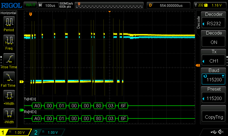
The displayed values correspond exactly to what is expected for a write datagram. You can also see very nicely that all bytes sent on the TX line also appear on the RX line and the RX buffer must therefore be cleared again after sending.
Reading the GCONF register generates these signals:
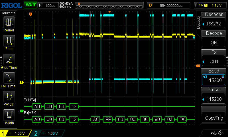
Here you can see very nicely the delay after sending the request datagram, which corresponds exactly to the time for the transmission of a byte.
Moving the stepper motor can be done in two different ways. For constant rotation, it is sufficient to write a value other than 0 into the VACTUAL register. This value indicates the motor speed in microsteps per time unit. The motor direction is controlled by the sign of VACTUAL. To turn the motor by an exact number of steps, I use the RMT (Remote Control) module. With this module it is possible to generate a precise sequence of pulses that rotate the motor by single steps via the STEP line of the TMC2208. The advantage of this method is that the CPU is not blocked while the signals are being sent.
To do this, the RMT module must first be initialised:
rmt_driver_install(tmc2208->driver_config.channel, 0, 0);
rmt_config_t config = RMT_DEFAULT_CONFIG_TX(tmc2208->driver_config.step_pin, tmc2208->driver_config.channel);
rmt_config(&config);
The function for generating and sending the signals is as follows:
// Allocate memory for the RMT items
rmt_item32_t* items = (rmt_item32_t*) pvPortMalloc(sizeof(rmt_item32_t) * steps);
if (items == NULL) {
	ESP_LOGE("RMT", "Failed to allocate memory for RMT items");
	return ESP_FAIL ;
}

// Configure the RMT items
for (int i = 0; i < steps; i++) {
	items[i].level0 = 1;
	items[i].duration0 = signal_duration;
	items[i].level1 = 0;
	items[i].duration1 = signal_duration;
}

ret = rmt_write_items(tmc2208->driver_config.channel, items, steps, true);

// Free the memory for the RMT items
vPortFree(items);

return ret;
The value of signal_duration indicates the number of ticks the signal is in the high or low state. With a peripheral bus (APB) clock of 80 MHz and a divider of 80 (default configuration), one tick corresponds to exactly 1 µs. The following picture shows the signal with a signal_duration of 100 ticks:
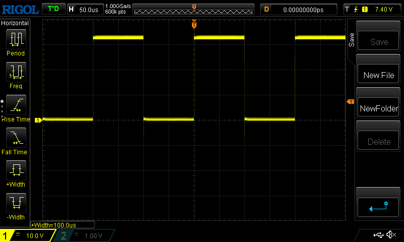
As expected, the pulse width is exactly 100 µs. The frequency of the pulses controls the speed at which the motor rotates.
The following list gives an overview of the functions of the stepper motor API. There is a little documentation in the source code, but this can certainly still be improved. :-)
esp_err_t (*init)(stepper_driver_t *handle);
esp_err_t (*clear_gstat)(stepper_driver_t *handle);

esp_err_t (*enable)(stepper_driver_t *handle);
esp_err_t (*disable)(stepper_driver_t *handle);
esp_err_t (*direction)(stepper_driver_t *handle, uint8_t direction);
esp_err_t (*steps)(stepper_driver_t *handle, uint32_t steps, uint32_t signal_duration);

esp_err_t (*set_vactual)(stepper_driver_t *handle, int32_t speed);
esp_err_t (*set_tpowerdown)(stepper_driver_t *handle, uint8_t tpowerdown);
esp_err_t (*set_stealthchop_thrs)(stepper_driver_t *handle, uint32_t tpwmthrs);
esp_err_t (*set_current)(stepper_driver_t *handle, uint16_t milliampere_run, uint8_t percent_hold);

esp_err_t (*set_microsteps_per_step)(stepper_driver_t *handle, stepper_driver_microsteps_t microssteps);
esp_err_t (*set_tbl)(stepper_driver_t *handle, uint8_t tbl);
esp_err_t (*set_toff)(stepper_driver_t *handle, uint8_t toff);
esp_err_t (*set_hysteresis)(stepper_driver_t *handle, uint8_t hstrt, uint8_t hend);

esp_err_t (*set_pwm_lim)(stepper_driver_t *handle, uint8_t pwm_lim);
esp_err_t (*set_pwm_reg)(stepper_driver_t *handle, uint8_t pwm_reg);
esp_err_t (*set_pwm_freq)(stepper_driver_t *handle, stepper_driver_pwm_freq_t pwm_freq);
esp_err_t (*set_pwm_grad)(stepper_driver_t *handle, uint8_t grad);
esp_err_t (*set_pwm_offset)(stepper_driver_t *handle, uint8_t offset);
esp_err_t (*disable_pwm_autograd)(stepper_driver_t *handle);
esp_err_t (*enable_pwm_autograd)(stepper_driver_t *handle);
esp_err_t (*disable_pwm_autoscale)(stepper_driver_t *handle);
esp_err_t (*enable_pwm_autoscale)(stepper_driver_t *handle);

esp_err_t (*read_register_gstat)(stepper_driver_t *handle);
esp_err_t (*read_register_tstep)(stepper_driver_t *handle);
esp_err_t (*read_register_drv_status)(stepper_driver_t *handle);
esp_err_t (*read_register_ioin)(stepper_driver_t *handle);
esp_err_t (*read_register_otp_read)(stepper_driver_t *handle);
esp_err_t (*read_register_mscntd)(stepper_driver_t *handle);
esp_err_t (*read_register_mscuract)(stepper_driver_t *handle);

esp_err_t (*dump_register_tstep)(stepper_driver_t *handle);
esp_err_t (*dump_register_drv_status)(stepper_driver_t *handle);
esp_err_t (*dump_register_ioin)(stepper_driver_t *handle);
esp_err_t (*dump_register_gconf)(stepper_driver_t *handle);
esp_err_t (*dump_register_otp_read)(stepper_driver_t *handle);
esp_err_t (*dump_register_chopconf)(stepper_driver_t *handle);
esp_err_t (*dump_register_pwmconf)(stepper_driver_t *handle);
esp_err_t (*dump_register_factory_conf)(stepper_driver_t *handle);
esp_err_t (*dump_register_mscuract)(stepper_driver_t *handle);
esp_err_t (*dump_register_pwm_scale)(stepper_driver_t *handle);
esp_err_t (*dump_register_pwm_auto)(stepper_driver_t *handle);
Finally, here is a brief example of how the component is used:
// Create new driver
stepper_driver_t *motor = stepper_driver_new_tmc2208(&config->stepper_driver_conf);
// Init driver
stepper_driver_init(motor);
// Clear status
stepper_driver_clear_gstat(motor);

stepper_driver_set_stealthchop_thrs(motor, 0);
stepper_driver_set_current(motor, 150, 100);
stepper_driver_set_microsteps_per_step(motor, MICROSTEPS_1);

stepper_driver_enable_pwm_autograd(motor);
stepper_driver_enable_pwm_autoscale(motor);
stepper_driver_set_pwm_reg(motor, 1);
stepper_driver_set_pwm_freq(motor, FREQ_2_512);
stepper_driver_enable(motor);

stepper_driver_steps(motor, 30000, 200);
The complete source code of the ESP32 component is available on GitHub. I would be very happy about any feedback or suggestions for improvement.