Control brightness of Raspberry Pi 7 inch display with integrated photoresistor
In this article, I will show you how to control the original 7 inch display of the Raspberry Pi with a photoresistor. The photoresistor is integrated directly into the display through a small modification and makes it possible to adjust the brightness of the display to the ambient brightness. This can be particularly useful if you are using the display in an environment where the brightness often varies.
Measuring analog signals with the Raspberry Pi
The simplest way to measure the brightness is using a photoresistor. With a voltage divider you could determine the value of the photoresistor at an analog input and thus determine the brightness. Unfortunately, the Raspberry Pi has no analog inputs. However, there is another way to measure an analog value with a digital input. This method is far from accurate, but it is sufficient for this purpose.
The trick is to transform the process of "measuring voltage" into a "measuring time", which is easily done with the Raspberry Pi. In addition to the photoresistor, only a capacitor is needed for this. The circuit for this looks like this:
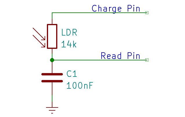
The measurement is performed in two steps:
- Discharging the capacitor: To do this, both pins are set to 0. This means that no further charge flows into the capacitor and the existing charge flows out via the Read Pin.
- Charging the capacitor: The Read Pin is switched to Input and the Charge Pin is set to 1. Now the capacitor is charged. The speed of charging depends on the current value of the photoresistor. The voltage at the Read Pin will now increase and will eventually exceed the threshold at which the value is recognized by the Raspberry Pi as a logic 1 (about 1.37 volts). This time span can be measured with the Raspberry Pi.
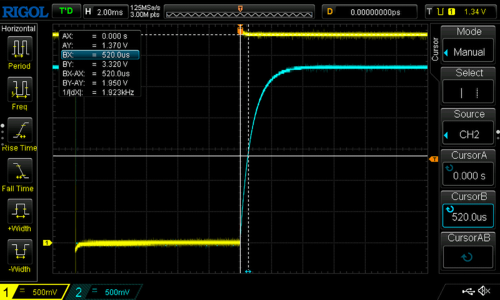
With this method it is possible to indirectly measure the actual value of the photoresistor and thus the brightness. On the oscilloscope you can observe this process very nicely:
The first picture shows the charging process at normal brightness. The yellow line is the charge pin and the blue line is the read pin. The charging time until the threshold value is reached is about 0.5 milliseconds.
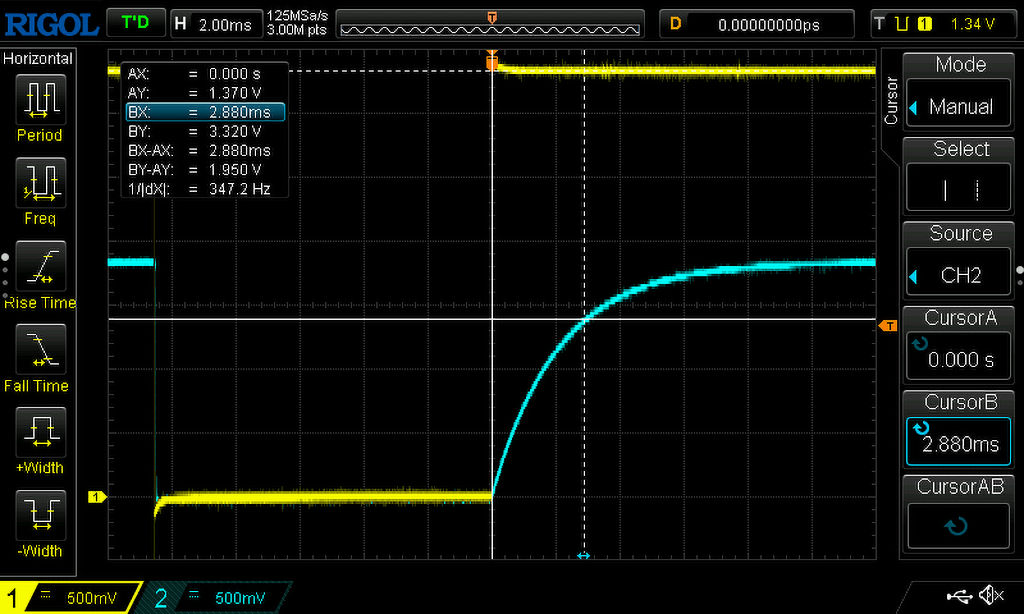
The following picture shows the charging process with less light. The charging time here is about 2.8 milliseconds.
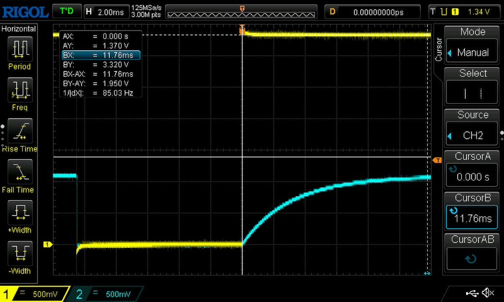
The last image shows the charging process in very low light. In this case, the threshold is not reached at all. This is because the internal resistance of the Raspberry Pi plays a role here, which forms a voltage divider together with the photoresistor. This has to be considered in the implementation, because you will need a timeout here. In my case I set this to 15 milliseconds.
Implementation of the brightness control
The brightness control for the Raspberry Pi display is programmed in C and uses the gpiod library to control the ports. First two packages have to be installed:
sudo apt install gpiod
sudo apt install libgpiod-dev
The first package provides some tools for communication with the Linux GPIO ports. The second library contains the necessary libraries and header files for C programming.
With these tools you can for example display the available GPIO devices. With the display connected, the list looks like this for me:
pi@raspberrypi:~ $ gpiodetect
gpiochip0 [pinctrl-bcm2835] (54 lines)
gpiochip1 [raspberrypi-exp-gpio] (8 lines)
gpiochip2 [7inch-touchscreen-p] (2 lines)
All lines can also be displayed for the Devices:
pi@raspberrypi:~ $ gpioinfo
gpiochip0 - 54 lines:
        line   0:     "ID_SDA"       unused   input  active-high
        line   1:     "ID_SCL"       unused   input  active-high
        line   2:       "SDA1"       unused   input  active-high
        line   3:       "SCL1"       unused   input  active-high
        line   4:  "GPIO_GCLK"       unused   input  active-high
        line   5:      "GPIO5"       unused   input  active-high
        line   6:      "GPIO6"       unused   input  active-high
        line   7:  "SPI_CE1_N"       unused   input  active-high
        line   8:  "SPI_CE0_N"       unused   input  active-high
        line   9:   "SPI_MISO"       unused   input  active-high
        line  10:   "SPI_MOSI"       unused   input  active-high
        line  11:   "SPI_SCLK"       unused   input  active-high
        line  12:     "GPIO12"       unused   input  active-high
        line  13:     "GPIO13"       unused   input  active-high
        line  14:       "TXD1"       unused   input  active-high
        line  15:       "RXD1"       unused   input  active-high
        line  16:     "GPIO16"       unused   input  active-high
        line  17:     "GPIO17"       unused   input  active-high
        line  18:     "GPIO18"  "brightness"  output  active-high [used]
        line  19:     "GPIO19"       unused   input  active-high
        line  20:     "GPIO20"       unused   input  active-high
        line  21:     "GPIO21"       unused   input  active-high
        line  22:     "GPIO22"       unused   input  active-high
        line  23:     "GPIO23"       unused   input  active-high
        line  24:     "GPIO24"  "brightness"  output  active-high [used]
        line  25:     "GPIO25"       unused   input  active-high
        line  26:     "GPIO26"       unused   input  active-high
        line  27:     "GPIO27"       unused   input  active-high
        line  28: "HDMI_HPD_N"        "hpd"   input   active-low [used]
        line  29: "STATUS_LED_G" "led0" output active-high [used]
        line  30:       "CTS0"       unused   input  active-high
        line  31:       "RTS0"       unused   input  active-high
        line  32:       "TXD0"       unused   input  active-high
        line  33:       "RXD0"       unused   input  active-high
        line  34:    "SD1_CLK"       unused   input  active-high
        line  35:    "SD1_CMD"       unused   input  active-high
        line  36:  "SD1_DATA0"       unused   input  active-high
        line  37:  "SD1_DATA1"       unused   input  active-high
        line  38:  "SD1_DATA2"       unused   input  active-high
        line  39:  "SD1_DATA3"       unused   input  active-high
        line  40:   "PWM0_OUT"       unused   input  active-high
        line  41:   "PWM1_OUT"       unused   input  active-high
        line  42:    "ETH_CLK"       unused   input  active-high
        line  43:   "WIFI_CLK"       unused   input  active-high
        line  44:       "SDA0"       unused   input  active-high
        line  45:       "SCL0"       unused   input  active-high
        line  46:   "SMPS_SCL"       unused   input  active-high
        line  47:   "SMPS_SDA"       unused  output  active-high
        line  48:   "SD_CLK_R"       unused   input  active-high
        line  49:   "SD_CMD_R"       unused   input  active-high
        line  50: "SD_DATA0_R"       unused   input  active-high
        line  51: "SD_DATA1_R"       unused   input  active-high
        line  52: "SD_DATA2_R"       unused   input  active-high
        line  53: "SD_DATA3_R"       unused   input  active-high
gpiochip1 - 8 lines:
        line   0:      "BT_ON"       unused  output  active-high
        line   1:      "WL_ON"       unused  output  active-high
        line   2:  "PWR_LED_R"       "led1"  output   active-low [used]
        line   3:    "LAN_RUN"       unused   input  active-high
        line   4:         "NC"       unused   input  active-high
        line   5:  "CAM_GPIO0" "cam1_regulator" output active-high [used]
        line   6:  "CAM_GPIO1"       unused  output  active-high
        line   7:         "NC"       unused   input  active-high
gpiochip2 - 2 lines:
        line   0:      unnamed "0.reg_bridge" output active-high [used]
        line   1:      unnamed      "reset"  output   active-low [used]
In the list you can see that I use ports 18 and 24 for the control.
To be able to control the brightness of the display, the corresponding driver must also be activated. This can be checked by the presence of the file /sys/class/backlight/10-0045/brightness. If not, edit the file /boot/config.txt with
sudo nano /boot/config.txt
and add the following line at the end:
dtoverlay=rpi-backlight
After a restart the driver is then active.
Now to the actual control. The code consists of three parts:
Discharging the capacitor
This is done by simply setting the two GPIO ports to 0 and waiting a certain amount of time.
ret = gpiod_line_request_output(gpio_charge_line, CONSUMER, 0);
if (ret != 0)
	goto release_lines;
ret = gpiod_line_request_output(gpio_read_line, CONSUMER, 0);
if (ret != 0)
	goto release_lines;

usleep(10000);

gpiod_line_release(gpio_charge_line);
gpiod_line_release(gpio_read_line);
Charging the capacitor and time measurement
Initially the Read Pin is configured so that an event is triggered on a rising edge. Then the Charge Pin is set to a 1. The function gpiod_line_event_wait then waits until either the event is triggered or a timeout occurs. The time until the event is measured with clock_gettime.
ret = gpiod_line_request_rising_edge_events(gpio_read_line, CONSUMER);
if (ret != 0)
	goto release_lines;

ret = gpiod_line_request_output(gpio_charge_line, CONSUMER, 1);
if (ret != 0)
	goto release_lines;

clock_gettime(CLOCK_MONOTONIC, &start);
ret = gpiod_line_event_wait(gpio_read_line, &ts); // Wait until the signal changes from 0 to 1
clock_gettime(CLOCK_MONOTONIC, &end);

if (ret > 0 && end.tv_nsec > start.tv_nsec) {
	y = end.tv_nsec - start.tv_nsec;
} else {
	y = READ_TIMEOUT;
}

gpiod_line_release(gpio_charge_line);
gpiod_line_release(gpio_read_line);
Adjusting the brightness
Since the measured values have a rather high scatter, the values are first smoothed. For this I use a method called exponential smoothing.
// Smooth values
y_stern = 0.1 * y + (1 - 0.1) * y_stern__prev;
y_stern__prev = y_stern;

// Map timing values to brightness values
brightness = (int)map_to_brightness( y_stern / 100000.0 ); // Map to 0 - 150

// Set brightness of display
set_brightness(brightness);
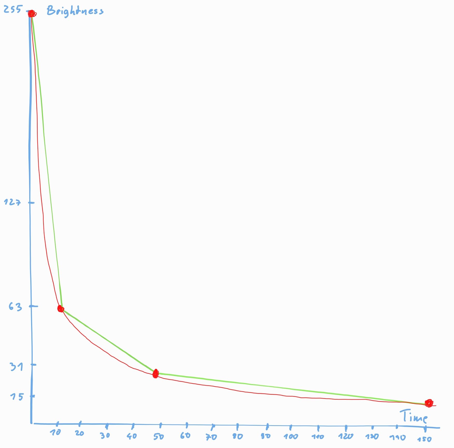
Then the time values are converted into brightness values. Since the relationship between the two values is not linear, I chose a pragmatic way. For this purpose, I have manually selected a brightness for some values, which seems to me to be suitable. I entered these values in a diagram and created a straight line equation from it for the individual ranges. This approximation worked well.
Finally, the calculated value is written to the file /sys/class/backlight/10-0045/brightness to set the brightness.
The source code for the control is available on GitHub.
Set up brightness control as a service
The brightness control is to be started automatically after booting. To do this, first copy the file created with the make command into the directory /usr/local/bin:
sudo cp brightness /usr/local/bin
Then a unit file is created with this command:
sudo nano /lib/systemd/system/brightness.service
and this content inserted:
[Unit]
 Description=Brightness
 After=multi-user.target

 [Service]
 Type=idle
 ExecStart=/usr/local/bin/brightness

 [Install]
 WantedBy=multi-user.target
The permissions for this file need to be adjusted:
sudo chmod 644 /lib/systemd/system/brightness.service
Finally, the service is activated:
sudo systemctl daemon-reload
sudo systemctl enable brightness.service
This sets up the service. After a restart, it should now start automatically.
Mounting the photoresistor in the display
Of course, the photoresistor does not necessarily have to be built into the display. But since my case for the weather station is already finished and I didn't want to print a new case, I decided for this variant. But you have to be aware that you lose all warranty claims!
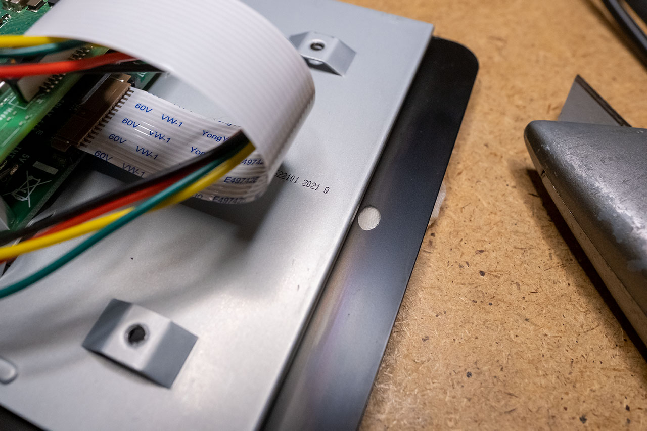
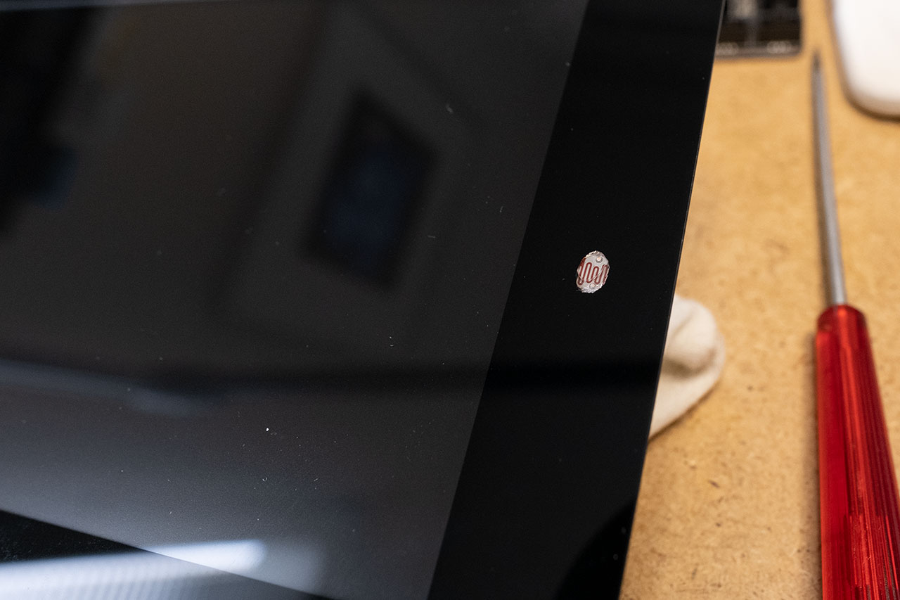
To control the brightness of the display optimally, the photoresistor should be as close as possible to the display. The Raspberry Pi 7 inch display has a relatively wide frame, which is well suited for this. To do this, you have to carefully scrape off the black paint on the back of the front glass on the narrow side of the display with a Stanley knife so that a small area the size of the photoresistor becomes transparent. You have to be very careful, since this paint can be scraped off very easily.
The next step is to glue the photoresistor onto the hole. I used a 2-component adhesive for this.
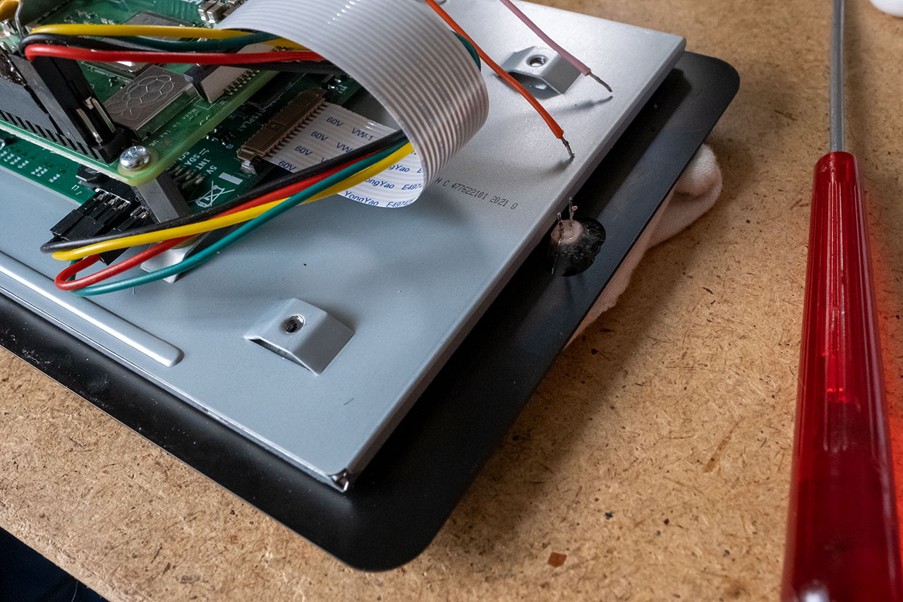
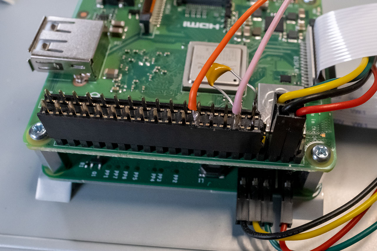
To prevent light shining through the scratched opening from behind, I masked the area with black tape. The rest of the "electronics", i.e. the capacitor, is soldered onto a female connector. Also the connecting wires for the photoresistor are soldered here. I used a 2x20 pin female connector, from which I just cut off a part, because the right pins are already occupied by the display.
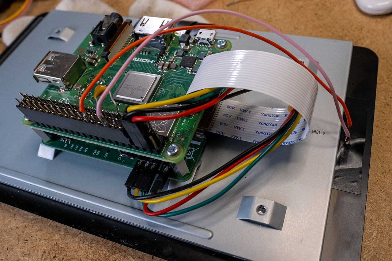
Here is another picture of the female connector.
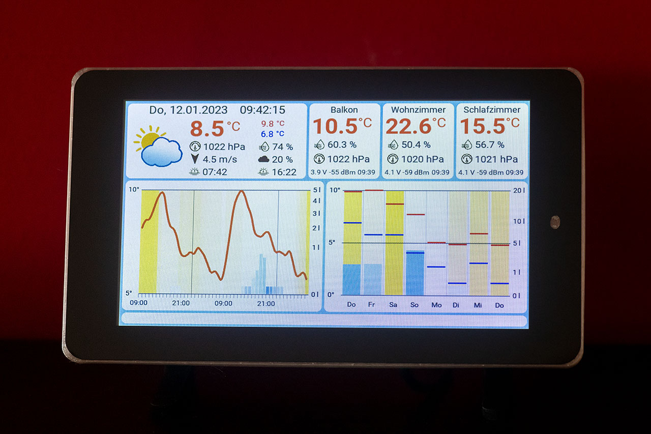
In the end, the display should look like this from the front:
This also completes the modification.
The Raspberry Pi display now automatically adjusts to the brightness of the environment. This is not only energy efficient, but also easy on the eyes. Have fun building your own!