Slave Clock Controller with ESP32-C3 and DRV8871 - Compact and Affordable
I have already built several controllers for slave clocks in the past, which generally work perfectly. Now, however, I have two more slave clocks on my desk, and my ambition was sparked to see if I could make the solution even more affordable and compact than my previous controllers.
The controller must meet several requirements:
- Must work for classic slave clocks as well as Bodet flip clocks, which require a separate power supply for the date motor
- Easy commissioning of the slave clock
- Must be suitable for 12 Volt and 24 Volt slave clocks
- Compact and as cheap as possible
- Simple assembly of the controller
So, I started looking for suitable components to implement this. I didn't want to change the fundamental design using a microcontroller, as this solution has proven itself well. A power reserve via a rechargeable battery was also a must-have.
The Components
Ultimately, only four modules are needed for the controller:
ESP32-C3
My previous microcontrollers, such as the LILYGO T-Display or a classic ESP32 DevKit board, work in principle, of course. However, these boards are quite large due to their many pins, and I actually only need two pins to control the H-bridge. If you look for smaller boards, you very quickly come across the ESP32-C3. I found a board on AliExpress that even features a tiny 0.42-inch OLED display. This is very helpful for directly reading the microcontroller's internal time and comparing it with the mechanical clock. In addition, there is a reset button and a boot button on the board; the boot button can also be used for other purposes after a program has started.
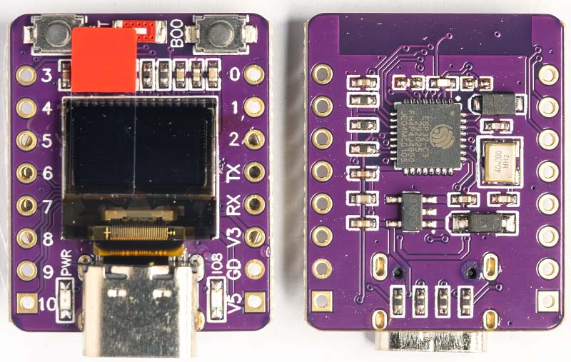
The ESP32-C3 is Espressif's first microcontroller with RISC-V architecture instead of the usual Xtensa Core. With its 32-bit RISC-V single-core processor, it reaches clock frequencies of up to 160 MHz.
Despite being a single-core, the C3 comes with the proven ESP32 features: WiFi 4 (802.11b/g/n), Bluetooth 5 LE, 400 KB SRAM, and extensive peripherals including SPI, I2C, UART, ADC, and PWM. This is more than sufficient for controlling a slave clock.
DRV8871 H-Bridge Driver
The DRV8871 is an H-bridge driver with up to 3.6 A peak current. The H-bridge consists of four N-Channel MOSFETs and is controlled via two logic inputs, enabling bidirectional motor control and PWM-based speed regulation.
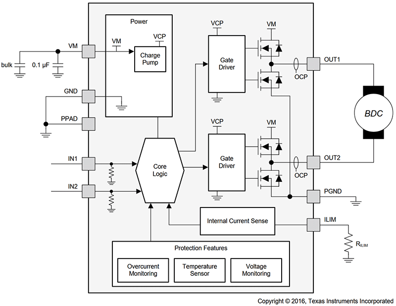
It is characterized by a wide operating voltage range, extending from a minimum of 6.5 V to a maximum of 45 V. This allows 12 Volt and 24 Volt slave clocks to be operated without any issues. Theoretically, a 48 Volt slave clock could also work, but I haven't found a step-up converter yet that can boost from 5 V to 45 V.
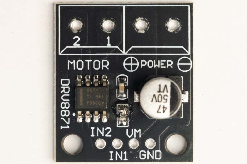
Control is significantly simpler than with the L293D. Only one power supply is required, and no enable inputs are needed. The inputs (IN1 and IN2) are reliably recognized as a logical 1 (High level) from a voltage of 1.5 V upwards, meaning the chip can be controlled by the ESP32 without problems.
TP4056
The TP4056 USB-C Li-Ion charging board is the standard when it comes to small modules with a USB-C connection. The maximum charging current is 1 A (adjustable via SMD resistor) and the cut-off voltage is 4.2 V.
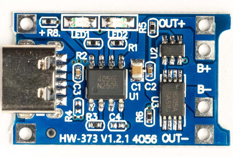
Unlike many other charging boards, this module also features deep discharge protection for the battery at 2.5 V. This means even a longer power failure is not a problem, and the battery is not damaged. Two LEDs indicate the charging status: Red during charging, Blue when the battery is fully charged.
Step-Up Converter SX1308
The SX1308 Step-Up Converter generates the necessary voltage for the slave clock. The input voltage range is 2 V to 24 V, and the output voltage can be regulated up to 28 V.
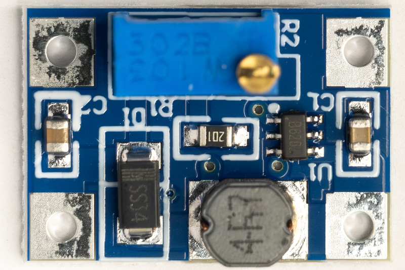
It is the smallest module I could find. The output voltage is adjusted using the potentiometer. However, you have to crank it for quite a while before anything happens. The actual adjustment range is then only a few turns.
The Circuit
The following diagram shows how the modules are connected. When the battery is charged, the TP4056 charge controller delivers a voltage of 4.2 V, which powers both the SX1308 Step-Up Converter and the ESP32-C3 module. The ESP32-C3 Development Board has a reverse polarity protection diode at the 5V input (approx. 0.7 V voltage drop), followed by the onboard ME6211 voltage regulator with 3.3 V output voltage. With a 4.2 V input voltage, approximately 3.1 V is available to the microcontroller. This is sufficient, as the ESP32-C3 operates from 3.0 V according to the datasheet.
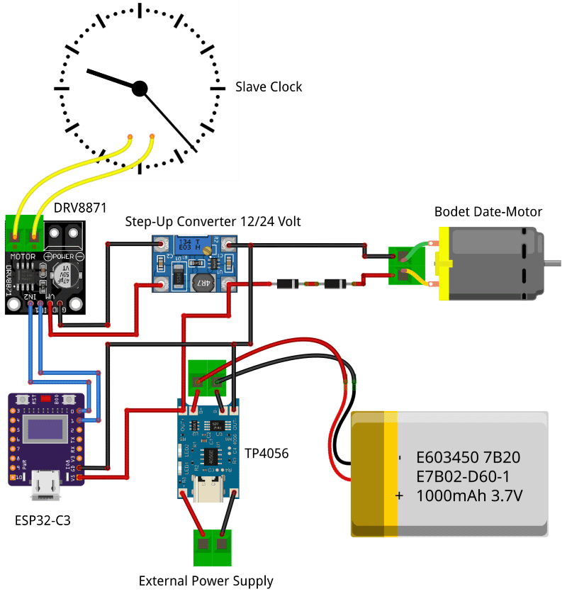
For the DC motor in the Bodet slave clocks with date display, 3 V are required. This is generated from the battery's 4.2 V by two diodes connected in series (2x 0.7 V ≈ 1.4 V voltage drop), resulting in a motor voltage of approx. 2.8 V.
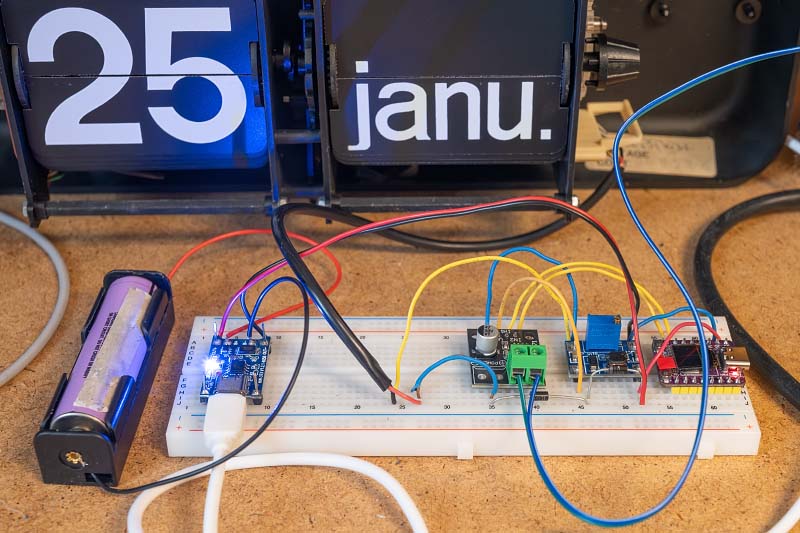
I have tested the setup with different clock types: two Bodet slave clocks with date display and a normal analog slave clock. The circuit works reliably with all clocks.
PCB (Printed Circuit Board)
Since the circuit is now running stably and, honestly, I no longer felt like tediously soldering everything together on perfboard every time, it was time for a professional PCB. I designed a compact carrier board in KiCad, onto which only the individual modules need to be soldered.
For the manufacturing of the PCBs, I received support from PCBWay, who sponsored this project. A big thank you at this point! The ordering process was very simple. Thanks to the PCBWay plugin for KiCad, I didn't have to manually export and upload Gerber files but could transmit the manufacturing data directly from the software with just one click.
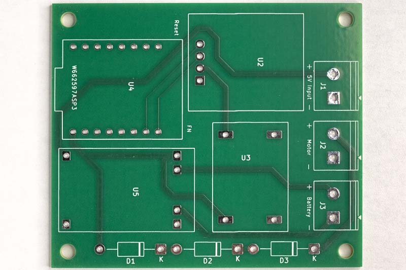
Only 5 days passed from the order to delivery via DHL, and the quality of the delivered PCBs is excellent, which made assembling the controller significantly easier than the previous wiring on perfboard.
The finished controller now looks like this:
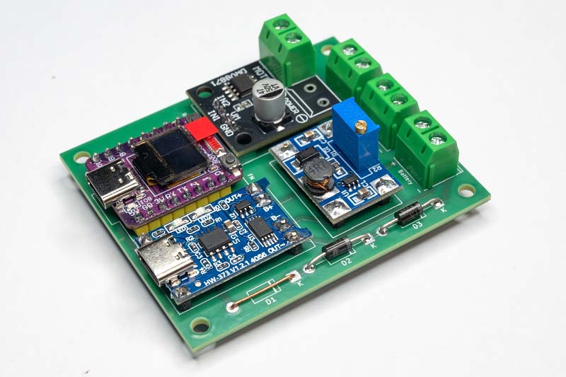
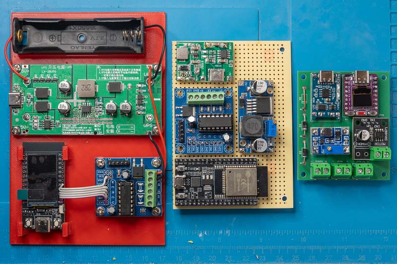
The comparison with earlier versions shows that the controller has become quite compact.
The layout is kept deliberately flexible:
- Standard Slave Clocks: For normal clocks, the additional diodes and the associated terminal are not required and can simply be left out.
- Power Supply: If you don't need a battery supply, you can omit the TP4056 charge controller. Instead, a wire jumper is soldered in, connecting the input and output (IN+ and OUT+) of the charge controller.
- Voltage Adaptation (Bodet): Without the charge controller, the supply voltage rises from 4.2 V to 5 V. This is relevant if a Bodet flip clock with date is being controlled. For this case, space for a third diode is provided on the PCB to reduce the voltage accordingly. If this is not needed, it is also simply replaced by a wire jumper.
The Control Software
The software is developed with the ESP-IDF Framework and consists of several components. Each component encapsulates specific functionality within its own C++ class. main.cpp acts as the central orchestration layer, initializing and connecting all components.
┌─────────────────────────────────────────────────────────────────┐
│                         main.cpp                                │
│                    (Orchestration)                              │
└─────────────────────────────────────────────────────────────────┘
        │              │                │                 │
        ▼              ▼                ▼                 ▼
┌─────────────┐ ┌──────────────┐ ┌─────────────┐ ┌─────────────────┐
│ SlaveClock  │ │   Display    │ │   Button    │ │ WifiProvisioner │
│             │ │              │ │             │ │                 │
│ • Motor     │ │ • OLED       │ │ • Debounce  │ │ • Captive Portal│
│   control   │ │ • Screensaver│ │ • Short/    │ │ • NTP Sync      │
│ • Time      │ │ • I2C        │ │   Long/     │ │ • Credentials   │
│   tracking  │ │              │ │   Double    │ │                 │
└─────────────┘ └──────────────┘ └─────────────┘ └─────────────────┘
      │               │                │                  │
      ▼               ▼                ▼                  ▼
   [GPIO]          [I2C]           [GPIO]           [WiFi/SNTP]
   DRV8871        SSD1306          Taster            Internet
SlaveClock
The SlaveClock class is the heart of the application. It controls the Lavet stepper motor via a DRV8871 H-bridge driver and stores the current hand position.
Impulse Generation: Slave clocks use a polarized stepper motor that performs one step with every change of polarity. The class therefore internally manages a _polarity_level, which is inverted after every pulse.
// Simplified representation of the pulse logic
if (_polarity_level) {
    gpio_set_level(_input1_pin, 1);
    gpio_set_level(_input2_pin, 0);
} else {
    gpio_set_level(_input1_pin, 0);
    gpio_set_level(_input2_pin, 1);
}
vTaskDelay(pdMS_TO_TICKS(_pulse_width_ms));
gpio_set_level(_input1_pin, 0);
gpio_set_level(_input2_pin, 0);
_polarity_level = !_polarity_level;
Time Tracking: The class stores the current hand position. With every call of update(), this is compared with the system time. If the hand position lags behind the system time, the corresponding number of pulses are sent to catch up:
int minutes_diff = SystemTime - HandPosition;
if (minutes_diff > 0) {
    sendPulses(minutes_diff);
    _clock_tm = timeinfo_now;  // Update hand position
}
LED Indicator: Optionally, a GPIO pin can be configured for an LED. This lights up during every pulse, providing visual feedback on the motor activity.
Display
The Display class encapsulates a small 0.42" OLED display (72×40 pixels) with an SSD1306 controller. Communication takes place via I2C using the u8g2 graphics library.
Layout: The display shows two pieces of information:
- Top line (small font): Status messages like "Booting...", "Connecting..." or "Time synched".
- Bottom line (large font): The current time in HH:MM:SS format.
Screensaver Function: An integrated FreeRTOS software timer automatically switches off the display after a configurable time. The timer runs in the background, independent of the main loop. If the display is switched on manually (e.g., via button press), the timer restarts automatically.
I2C-Bus-Recovery: A particular problem with microcontroller projects is that a reset during an ongoing I2C transmission can leave the bus in an invalid state. The slave (the display) then waits endlessly for further data and blocks the bus. The display initialization therefore performs "Clock Cycling" before the actual setup: 9 clock pulses on the SCL line followed by a STOP condition. This frees a potentially hung slave and restores the bus to a defined state.
Button
The Button class runs as an independent FreeRTOS task in the background and handles the complete evaluation of a push button, including debouncing and detection of different press patterns.
Debouncing: Mechanical buttons bounce, meaning that when pressed and released, multiple switching impulses occur briefly. The class ignores state changes that occur within 50ms of the last change.
Event Types:
- Short Press: Pressed and released in < 500ms
- Long Press: Held for > 500ms
- Double Click: Two short presses within 400ms
Callback-based API: Instead of actively polling the button state, the application registers callback functions that are called upon events. Using std::function allows for modern lambda expressions:
button.onShortPress([&oled](Button::PressType) {
    oled.togglePower();
});
The lambda expression passes the oled variable by reference ([&oled]) and can thus access the display object directly without the need for global variables.
Wifi Provisioning
The Wifi Provisioning component solves a fundamental problem of IoT devices: How do you configure the WiFi credentials when the device doesn't have a network connection yet?
Captive Portal: Upon the first start (or if no valid credentials are stored), the ESP32 opens its own Access Point named "Slave Clock Setup". If a smartphone or laptop connects to this network, a configuration page is automatically displayed. This webpage shows:
- A list of available WiFi networks (sorted by signal strength, without duplicates)
- Input field for the WiFi password
- Selection of the time zone
- Input of the current hand position
Initial Setup Process:
┌────────────────────────┐
│ ESP32 starts as        │
│ Access Point           │
└───────────┬────────────┘
            ▼
┌────────────────────────┐
│ User connects to       │
│ "Slave Clock"          │
└───────────┬────────────┘
            ▼
┌────────────────────────┐
│ Captive Portal shows   │
│ configuration page     │
└───────────┬────────────┘
            ▼
┌────────────────────────┐
│ User selects WiFi,     │
│ enters password        │
└───────────┬────────────┘
            ▼
┌────────────────────────┐
│ ESP32 connects to      │
│ home WiFi              │
└────────────────────────┘
Time Synchronization: After a successful WiFi connection, the component synchronizes the system time via the Simple Network Time Protocol (SNTP) with an internet time server. The configured time zone is taken into account so that the system time is automatically available in local time.
Program Flow
The main loop is kept deliberately simple: Once per second, the current time is fetched, displayed on the screen, and the slave clock is updated. The entire complexity—debouncing, screensaver timer, WiFi events—runs in the background components.
                    ┌─────────────┐
                    │    Start    │
                    └──────┬──────┘
                           ▼
              ┌────────────────────────┐
              │ Initialize Components  │
              │ • SlaveClock           │
              │ • Display              │
              │ • Button               │
              └────────────┬───────────┘
                           ▼
              ┌────────────────────────┐
              │ WiFi Credentials       │
              │ available?             │
              └────────────────────────┘
                    │             │
                   Yes            No
                    │             │
                    │             ▼
                    │    ┌─────────────────┐
                    │    │ Start Captive   │
                    │    │ Portal          │
                    │    └────────┬────────┘
                    │             │
                    ▼             ▼
              ┌────────────────────────┐
              │ Connect to WiFi        │
              └────────────┬───────────┘
                           ▼
              ┌────────────────────────┐
              │ NTP Time Sync          │
              └────────────┬───────────┘
                           ▼
              ┌────────────────────────┐
              │ Set Hand Position      │
              └────────────┬───────────┘
                           ▼
                 ┌────────────────┐
           ┌─────│    Main Loop   │◄────┐
           │     └────────────────┘     │
           │                            │
           ▼                            │
    ┌──────────────┐                    │
    │ Display Time │                    │
    │ Update Clock │────────────────────┘
    └──────────────┘    (every second)
The code for the slave clock controller is available on GitHub.
Conclusion
After several iterations, I am very satisfied with the final PCB. The combination of ESP32-C3 and DRV8871 works reliably and costs only a few Euros to manufacture. The controller synchronizes automatically via NTP and can even withstand power failures.
The next Bodet flip clocks are already waiting and will be converted soon, but more on that in a separate article.