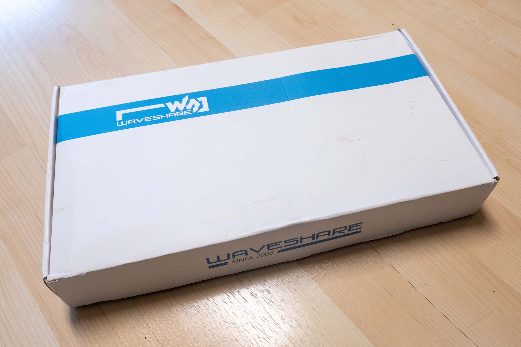
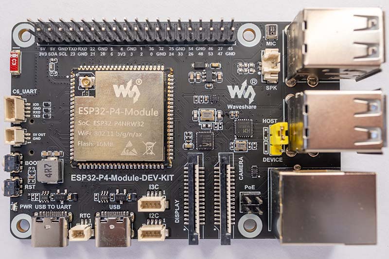
Waveshare ESP32-P4-Module-DEV-KIT-C: Compact Development Board with a 10.1-Inch DSI Display
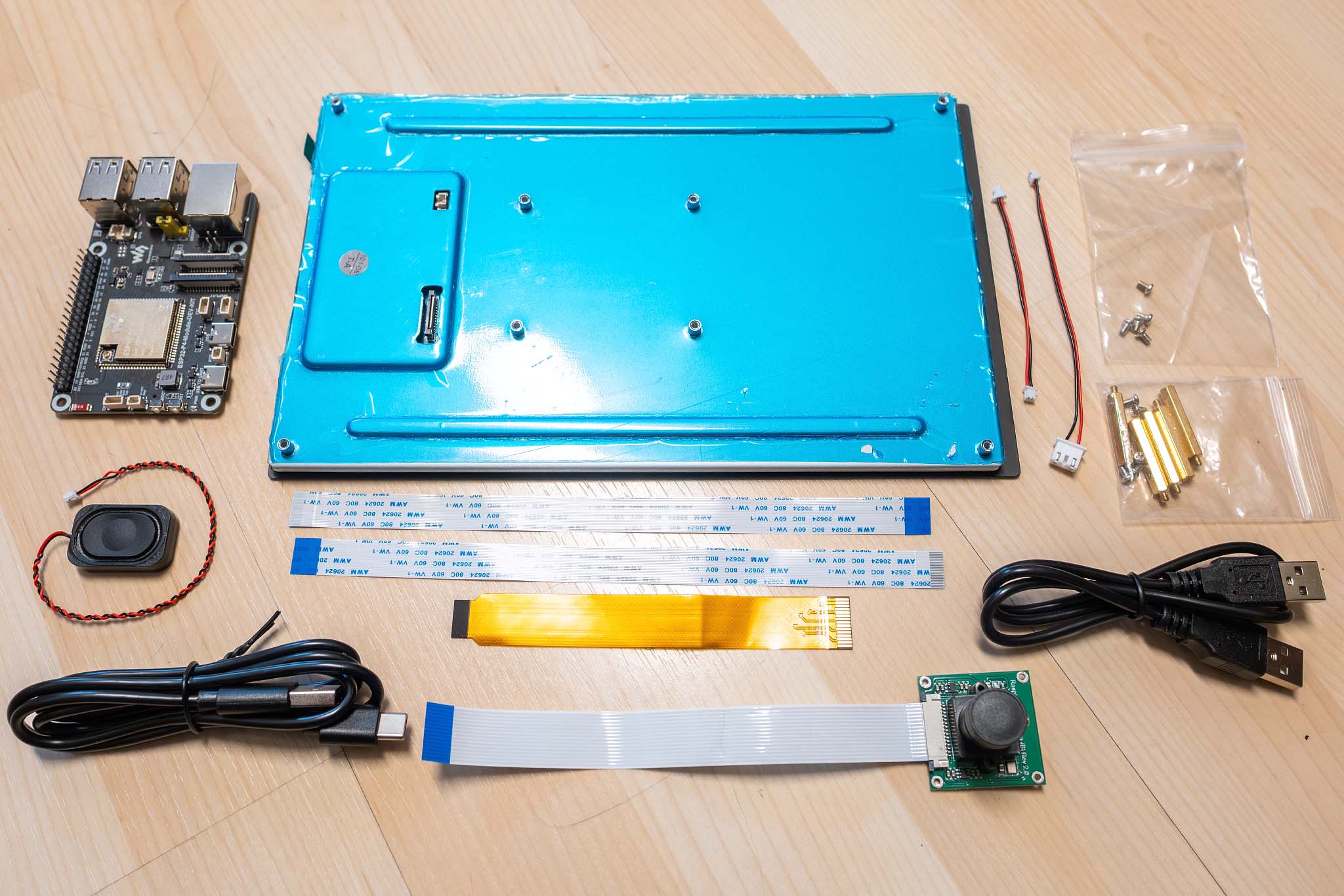
After recently taking a look at the CrowPanel Advance 7" ESP32-P4, today I would like to introduce you to the Waveshare ESP32-P4-Module-DEV-KIT-C. This kit differs fundamentally from other "all-in-one" solutions, as the display and microcontroller are two separate components that can also be swapped out for other models. Therefore, Waveshare offers the kit in different variants: DEV-KIT-A without a display, DEV-KIT-B with a 7-inch display and camera, or the DEV-KIT-C presented here, featuring a large 10.1-inch display and camera.
At first glance, the technical specifications of the DEV-KIT-C read very impressively:
- SoC: Espressif ESP32-P4 (Dual-Core RISC-V @360 MHz + LP-Core @40 MHz)
- Coprozessor: ESP32-C6 (WiFi 6, Bluetooth 5.4, connected via SDIO)
- Memory: 32 MB PSRAM, 16 MB Flash
- Interfaces:
- MIPI-DSI (2-Lane, 22-Pin FPC Connector)
- MIPI-CSI (2-Lane, 22-Pin FPC Connector for cameras up to 1080p)
- 4x USB 2.0 Type-A Ports (Host-Mode)
- 1x USB Type-C (OTG/Programming)
- 100 Mbps Ethernet (RJ45)
- 40-Pin GPIO Header (compatible with the Raspberry Pi layout)
- Audio: ES8311 Codec, NS4150B Class-D amplifier (3W @ 4Ω)
- Peripherals: microSD slot, battery connector for RTC, I2C, SPI, UART, I2S
- Power Supply: USB-C or 5V via GPIO header, optional PoE module
- Display: DSI 10.1-inch, IPS panel with 800 × 1280 pixels, 800:1 contrast ratio, and 400 cd/m2 brightness
- Camera: 5 Megapixel (RPi Camera B) with manual focus
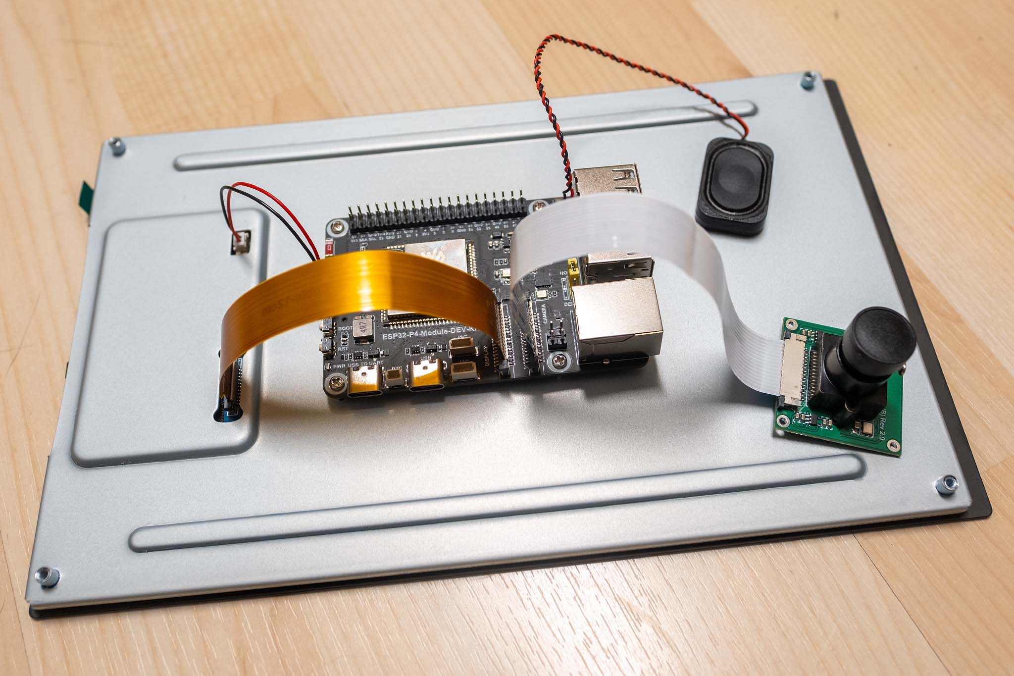
At first glance at the Waveshare ESP32-P4-Module, you immediately notice that it looks just like a Raspberry Pi. The board uses the exact same dimensions (85mm x 56mm), the same mounting hole positions, and even the layout of the primary connectors is modeled after the Raspberry Pi layout. The 40-pin GPIO header sits in the exact same spot, the four USB ports and the Ethernet jack are right where you'd expect them on a Pi, and even the FPC connectors for the camera (CSI) and display (DSI) are in the same locations as on the Raspberry Pi.
Waveshare has essentially created a kind of "Raspberry Pi pin-compatible microcontroller," but with one crucial difference: Instead of a Linux-capable ARM SoC, a 360 MHz RISC-V microcontroller with real-time capabilities operates here. You get the mechanical compatibility of a Raspberry Pi combined with the advantages of an embedded system, providing deterministic response times, direct hardware access without operating system overhead, and significantly lower power consumption.
However, electrical compatibility is only partially given. While the pin layout is identical, the GPIOs of ESP32 microcontrollers operate at 3.3V logic levels. Raspberry Pi HATs (Hardware Attached on Top) designed for 3.3V should theoretically work with it. But, of course, the software drivers have to be rewritten for the ESP-IDF.
The ESP32-P4-Module-DEV-KIT
The heart of the board is the large ESP32-P4-Module, which Waveshare developed in-house. This module integrates everything needed for high-performance applications:
- ESP32-P4 SoC: 360 MHz RISC-V dual-core processor with FPU and DSP extensions, 32 MB PSRAM integrated directly into the package
- ESP32-C6-MINI-1: Coprocessor for WiFi 6 (802.11ax), Bluetooth 5.4, and Zigbee/Thread (802.15.4)
- 16 MB NOR Flash: Onboard flash memory for firmware and application data
- IPEX Connector: Connection for an external antenna for WiFi/Bluetooth
The connection between the ESP32-P4 and the ESP32-C6 is established via the SDIO interface. The ESP-Hosted-MCU firmware runs over this connection, which I previously described in my CrowPanel Display review: The C6 acts purely as a Wi-Fi adapter, while the P4 transparently passes network commands through via SDIO. This greatly simplifies development for the P4. The familiar ESP-IDF WiFi functions are available without any changes, and the fact that the C6 handles the actual wireless communication in the background remains completely hidden.
Besides this module, the following components are located on the DEV-KIT:
Programming and USB:
- CH343P USB-to-UART Bridge: This dedicated chip ensures a reliable serial connection for flashing and debugging.
- CH334F USB Hub Controller: Since the ESP32-P4 only features one native USB 2.0 port, this hub controller expands the connections to four full-fledged Type-A receptacles. You can connect a USB flash drive, a mouse, or a keyboard here, for example.
- FSUSB42UMX USB Multiplexer: Switches the USB data path between the P4's native USB port and the CH343P UART chip.
Network:
- IP101GRI Ethernet PHY: A fully-featured 100 Mbps Fast Ethernet PHY chip.
- HBJ-6117ANL RJ45 Jack: Integrated network jack with magnetics and PoE support. Waveshare offers a separate PoE module that allows the board to be supplied with both network data and power via a single Ethernet cable.
Audio:
- ES8311 Audio Codec: 24-bit ADC/DAC by Everest Semiconductor, interfaced via I²S (GPIO9–GPIO13) and I²C (GPIO7/GPIO8). Supports sample rates from 8 kHz to 96 kHz.
- NS4150B Class-D Amplifier: 3W @ 4Ω output power with low quiescent current consumption, controllable via GPIO53 (PA_CTRL).
- MEMS Microphone: Onboard microphone (MIC_P/MIC_N) connected directly to the ES8311.
- SH1.0 Speaker Connector: 2-pin connector for an 8Ω speaker, which is included in the scope of delivery.
Memory and Peripherals:
- microSD Slot: Interfaced via SDIO 3.0 (GPIO39–GPIO45). Significantly faster than SPI-based SD card solutions.
- RTC Battery Connector: The ESP32-P4 has a real-time clock integrated directly into its Low-Power subsystem (LP-Core). The battery connector therefore supplies power directly to the VDD_RTC pin of the chip. Waveshare explicitly points out that this connector is only designed for rechargeable RTC batteries (e.g., ML2032 or LIR2032)! The board charges the battery as soon as it is supplied with power. A standard CR2032 coin cell would be overcharged and destroyed here.
- Boot and Reset Buttons: Classic tactile switches for GPIO0 (Boot) and CHIP_PU (Reset).
- Status LED: Simple power/status LED on GPIO35.
Display and Camera:
- 15-Pin FPC Connector (MIPI-DSI): 2-lane MIPI-DSI connector for displays. The data lines DSI_D0 and DSI_D1 as well as the clock are routed directly from the ESP32-P4 module. Additionally, GPIO7 and GPIO8 (I²C) are available at the connector to address the display's touch controller.
- 15-Pin FPC Connector (MIPI-CSI): 2-lane MIPI-CSI connector for cameras. Compatible with Raspberry Pi camera modules (OV5647, IMX219, etc.). I²C lines (CSI_IO0/IO1) for camera configuration are routed here as well.
40-Pin GPIO Header:
The 40-pin header is arguably the board's most important expansion port. The pinout is based on the Raspberry Pi layout, allowing the use of RPi-compatible cases and accessories. The following diagram illustrates the similarity of the two connectors:
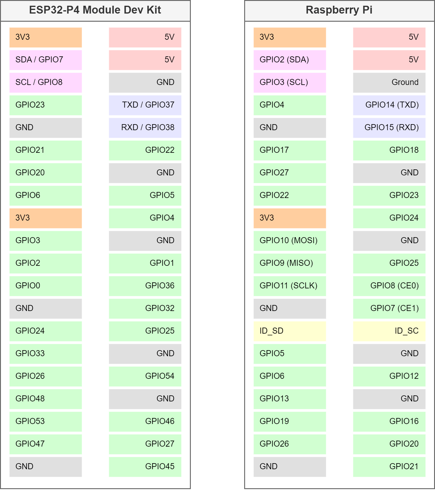
As mentioned above, the GPIO header is compatible with the Raspberry Pi in terms of layout, but not electrically. All GPIOs on ESP32 microcontrollers operate at 3.3V logic levels. Therefore, no Raspberry Pi HATs that operate with 5V signals may be used, as this would destroy the P4!
ESP32-C6 UART Port:
The UART lines of the ESP32-C6 are accessible via a small SH1.0 4-pin connector. This allows the C6 to be reflashed at any time using a simple USB-to-serial adapter, entirely independent of the P4. For instance, as soon as Espressif integrates the ESP-NOW protocol into the ESP-Hosted-MCU, a quick firmware update of the C6 is all it takes. This is a decisive advantage over the CrowPanel Advance ESP32-P4 Display, which lacks this feature, making a future update of the ESP-Hosted firmware fundamentally impossible on that device.
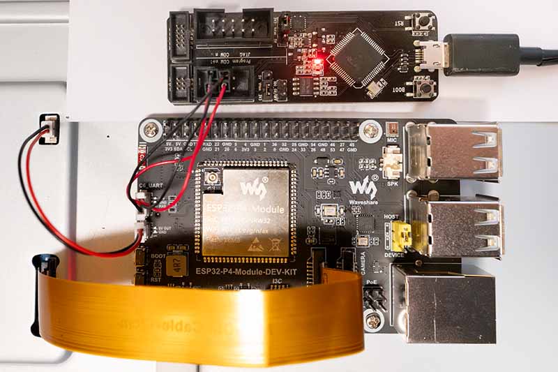
Unfortunately, Waveshare does not include a corresponding cable with the display. However, I coincidentally found a matching connector in my parts bin, built a makeshift cable, and connected the board to my old ESP-Prog board.
ESP-ROM:esp32c6-20220919
Build:Sep 19 2022
rst:0x1 (POWERON),boot:0xc (SPI_FAST_FLASH_BOOT)
SPIWP:0xee
mode:DIO, clock div:2
load:0x40875720,len:0x163c
load:0x4086c110,len:0xe84
load:0x4086e610,len:0x2f74
entry 0x4086c11c
I (23) boot: ESP-IDF v5.4-dev-3602-ga97a7b0962 2nd stage bootloader
I (24) boot: compile time Oct 18 2024 14:21:41
I (24) boot: chip revision: v0.2
I (25) boot: efuse block revision: v0.3
I (29) boot.esp32c6: SPI Speed      : 80MHz
I (33) boot.esp32c6: SPI Mode       : DIO
I (36) boot.esp32c6: SPI Flash Size : 4MB
I (40) boot: Enabling RNG early entropy source...
I (45) boot: Partition Table:
I (47) boot: ## Label            Usage          Type ST Offset   Length
I (54) boot:  0 nvs              WiFi data        01 02 00009000 00004000
I (60) boot:  1 otadata          OTA data         01 00 0000d000 00002000
I (67) boot:  2 phy_init         RF data          01 01 0000f000 00001000
I (73) boot:  3 ota_0            OTA app          00 10 00010000 00180000
I (80) boot:  4 ota_1            OTA app          00 11 00190000 00180000
I (86) boot: End of partition table
I (89) esp_image: segment 0: paddr=00010020 vaddr=420c0020 size=316d4h (202452) map
I (135) esp_image: segment 1: paddr=000416fc vaddr=40800000 size=0e91ch ( 59676) load
I (149) esp_image: segment 2: paddr=00050020 vaddr=42000020 size=b8f30h (757552) map
I (294) esp_image: segment 3: paddr=00108f58 vaddr=4080e91c size=12500h ( 75008) load
I (311) esp_image: segment 4: paddr=0011b460 vaddr=40820e20 size=03c94h ( 15508) load
I (322) boot: Loaded app from partition at offset 0x10000
I (322) boot: Disabling RNG early entropy source...
I (332) cpu_start: Unicore app
I (341) cpu_start: Pro cpu start user code
I (341) cpu_start: cpu freq: 160000000 Hz
I (341) app_init: Application information:
I (341) app_init: Project name:     network_adapter
I (345) app_init: App version:      release/ng-v1.0.2-330-g83efce6
I (351) app_init: Compile time:     Oct 18 2024 14:21:32
I (356) app_init: ELF file SHA256:  40ff50890...
--- Warning: Checksum mismatch between flashed and built applications. Checksum of built application is ffcdf9ce083e5e2039400a42c885f3fe41393f85c813c5993136e6e9dda0b1b7
I (361) app_init: ESP-IDF:          v5.4-dev-3602-ga97a7b0962
I (366) efuse_init: Min chip rev:     v0.0
I (370) efuse_init: Max chip rev:     v0.99
I (374) efuse_init: Chip rev:         v0.2
I (378) heap_init: Initializing. RAM available for dynamic allocation:
I (384) heap_init: At 408320B0 len 0004A560 (297 KiB): RAM
I (389) heap_init: At 4087C610 len 00002F54 (11 KiB): RAM
I (394) heap_init: At 50000000 len 00003FE8 (15 KiB): RTCRAM
I (400) spi_flash: detected chip: generic
I (403) spi_flash: flash io: dio
W (406) spi_flash: Detected size(8192k) larger than the size in the binary image header(4096k). Using the size in the binary image header.
I (419) sleep_gpio: Configure to isolate all GPIO pins in sleep state
I (425) sleep_gpio: Enable automatic switching of GPIO sleep configuration
I (431) coexist: coex firmware version: 49d5b702e
I (450) coexist: coexist rom version 5b8dcfa
I (450) main_task: Started on CPU0
I (450) main_task: Calling app_main()
I (450) fg_mcu_slave: *********************************************************************
I (457) fg_mcu_slave:                 ESP-Hosted-MCU Slave FW version :: 0.0.6
I (466) fg_mcu_slave:                 Transport used :: SDIO only
I (473) fg_mcu_slave: *********************************************************************
I (481) fg_mcu_slave: Supported features are:
I (485) fg_mcu_slave: - WLAN over SDIO
I (489) h_bt: - BT/BLE
I (491) h_bt:    - HCI Over SDIO
I (494) h_bt:    - BLE only
I (496) fg_mcu_slave: capabilities: 0xd
I (500) fg_mcu_slave: Supported extended features are:
I (505) h_bt: - BT/BLE (extended)
I (508) fg_mcu_slave: extended capabilities: 0x0
I (516) h_bt: ESP Bluetooth MAC addr: a0:85:e3:af:7c:16
I (517) BLE_INIT: Using main XTAL as clock source
I (526) BLE_INIT: ble controller commit:[5bc682c]
W (527) BLE_INIT: BLE modem sleep is enabled
I (530) BLE_INIT: Bluetooth MAC: a0:85:e3:af:7c:16
I (535) phy_init: phy_version 320,348a293,Sep  3 2024,16:33:12
I (599) phy: libbtbb version: 04952fd, Sep  3 2024, 16:33:30
I (600) SDIO_SLAVE: Using SDIO interface
I (600) SDIO_SLAVE: sdio_init: sending mode: SDIO_SLAVE_SEND_STREAM
I (603) SDIO_SLAVE: sdio_init: ESP32-C6 SDIO RxQ[20] timing[0]
After a reset, the ESP32-C6 responds as expected. Here you can see how the ESP-Hosted-MCU boots on the C6.
Further detailed information about the ESP32-P4-Module can be found in the Waveshare Wiki. It also provides an in-depth explanation of development using the ESP-IDF framework and Visual Studio Code.
10.1-Inch MIPI-DSI Touch Display
The DEV-KIT-C includes an excellent 10.1-inch MIPI-DSI display with a resolution of 800x1280 pixels in portrait format. The display is based on a high-quality IPS panel with 178° viewing angles and 400 cd/m² brightness. The colors remain stable even from oblique viewing angles, and the contrast does not wash out.
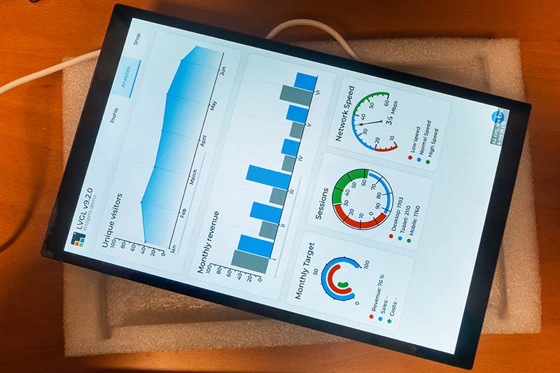
A special quality feature is the optical bonding: The cover glass is glued directly to the LCD panel without an air gap. The result is significantly better contrast, richer colors, and vastly improved readability under direct sunlight. At the same time, this construction prevents dust from getting between the glass and the panel.
The touch functionality is based on a capacitive 10-point touch screen, driven via I²C. The tempered cover glass achieves a hardness rating of 6H, which is considerably more scratch-resistant than normal glass.
The connection to the ESP32-P4 is made via a 22-pin FPC cable for MIPI-DSI. The display supports up to a 60 Hz refresh rate over the 2-lane MIPI-DSI connection.
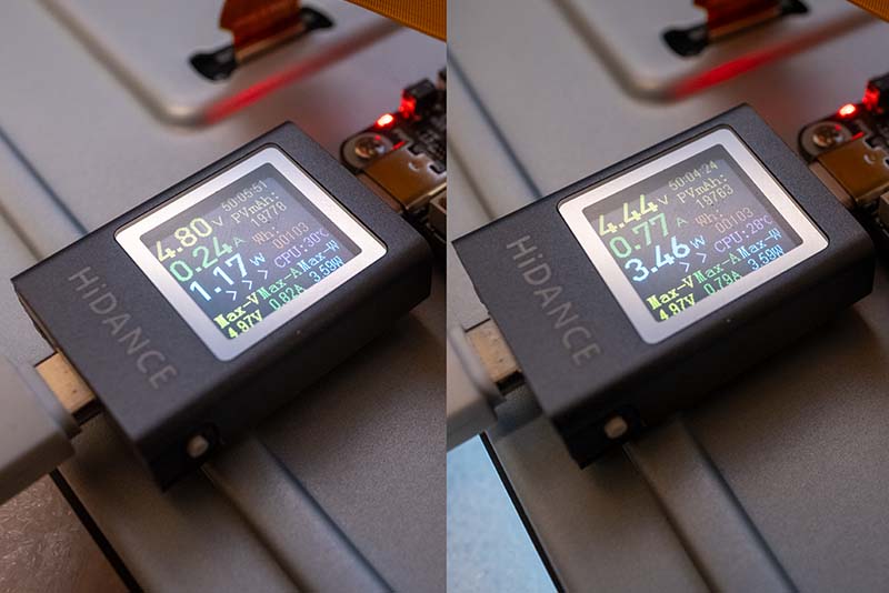
The following image shows the board's power consumption with the display turned off and at full brightness:
Besides the 10.1-inch display, Waveshare also offers a 7-inch variant (DEV-KIT-B) with 1024x600 pixels in landscape format. The Waveshare Wiki contains detailed information about the display, including how to connect it to a Raspberry Pi, for example.
RPi Camera (B)
The DEV-KIT-A, DEV-KIT-B, and DEV-KIT-C all include the Raspberry Pi Camera (B). The camera is based on the OV5647 sensor by Omnivision with a 5-megapixel resolution and supports video recording up to 1080p.
- Sensor: OV5647, 1/4 inch
- Resolution: 5 Megapixels, 1080p video
- Lens: 6mm focal length, F2.0 aperture
- Field of view: 60.6° diagonal
- Focus: Adjustable (manual)
- Dimensions: 32mm x 32mm
- Connection: 15-pin FFC cable (15cm)
The camera is compatible with the MIPI-CSI port of the ESP32-P4-Module-DEV-KIT and connects via the included ribbon cable. There is also a Wiki page for the camera, but it only covers Raspberry Pi topics.
LVGL with the ESP32-P4-Module-DEV-KIT and ESP-IDF
Developing graphical user interfaces with the ESP32-P4 Module DEV KIT is not fundamentally different from classic ESP32 development with parallel RGB displays. The main difference lies in the use of MIPI-DSI instead of the parallel RGB565 interface, which is common on ESP32-S3 boards.
MIPI-DSI is a high-speed serial standard originally developed for smartphones. Unlike parallel RGB interfaces, which require 16-24 data lines plus additional control signals, MIPI-DSI transmits the image data over just a few differential pairs (typically 1-4 "lanes"). Each lane consists of a differential pair (D+ and D-) and can achieve data rates ranging from several hundred megabits per second up to several gigabits per second. The ESP32-P4 features a native MIPI-DSI controller that supports up to 4 lanes. The Waveshare 10.1" display utilizes a 2-lane configuration with 1500 Mbps per lane, which is sufficient for 1280x800 pixels at 60 Hz.
Waveshare provides some code examples for the ESP32-P4-Module-DEV-KIT, including ones for LVGL, but these use Waveshare-specific components and BSP libraries. For my demo, however, I only wanted to use Espressif components from the ESP Component Registry. The application is very minimalist and simply controls the brightness of the backlight.
The layout was created using EEZ Studio and contains only the slider, a label with the brightness value, and an action that is called upon every change. The structure of the application is as follows:
lvgl_demo_waveshare/
├── .gitignore
├── CMakeLists.txt
├── partitions.csv
├── sdkconfig
├── sdkconfig.defaults
│
├── main/
│   ├── CMakeLists.txt
│   ├── idf_component.yml
│   ├── main.cpp
│   ├── display.c                  (Initialisierung I2C, Display, Touch, LVGL)
│   ├── display.h
│   └── ui/                        (EEZ Studio Code)
│       ├── ui.h
│       ├── ui.c
│       ├── screens.h
│       ├── screens.c
│       ├── styles.h
│       ├── styles.c
│       ├── images.h
│       ├── images.c
│       ├── fonts.h
│       ├── actions.h
│       ├── vars.h
│       └── structs.h
│
├── eez-studio/                     (EEZ Studio Projekt)
│
└── managed_components/             (ESP-IDF Komponenten)
    ├── lvgl__lvgl/
    ├── espressif__cmake_utilities/
    ├── espressif__esp_lcd_touch/
    ├── espressif__esp_lcd_touch_gt911/
    ├── espressif__esp_lvgl_port/
    └── espressif__esp_lcd_jd9365/
The project components are defined in the idf_component.yml file:
## IDF Component Manager Manifest File
##
## Only espressif and lvgl components are used.
##
dependencies:
  idf:
    version: '>=5.5.0'

  ## LVGL 8.x graphics library
  lvgl/lvgl:
    version: "8.4.*"

  ## ESP LVGL Port - integrates LVGL with ESP-IDF
  ## Handles LVGL task, display driver, touch input
  espressif/esp_lvgl_port:
    version: "^2"

  ## GT911 capacitive touch controller driver
  espressif/esp_lcd_touch_gt911:
    version: "^1"

  ## JD9365 MIPI DSI LCD panel driver (handles DBI commands + DPI panel)
  espressif/esp_lcd_jd9365:
    version: "^2"
Each component has a specific task:
- lvgl/lvgl: The actual LVGL graphics library (version 8.4)
- espressif/esp_lvgl_port: The integration layer between ESP-IDF and LVGL - manages the LVGL task, display buffers, and touch input
- espressif/esp_lcd_touch_gt911: Driver for the Goodix GT911 touch controller
- espressif/esp_lcd_jd9365: Driver for the JD9365 display controller (supports MIPI-DSI + DBI commands)
By far the most complex part of the program is the hardware initialization. It proceeds in several steps, which I would like to explain in a bit more detail here:
I2C-Bus Initialization
The I2C bus is required for two components: the touch controller (GT911) and the backlight controller. Both devices share the same bus:
#define I2C_SCL_PIN         GPIO_NUM_8
#define I2C_SDA_PIN         GPIO_NUM_7
#define I2C_PORT_NUM        I2C_NUM_0
#define I2C_CLK_SPEED_HZ    400000

static esp_err_t init_i2c(void)
{
    ESP_LOGI(TAG, "Initializing I2C bus (SCL=%d, SDA=%d, %d Hz)",
             I2C_SCL_PIN, I2C_SDA_PIN, I2C_CLK_SPEED_HZ);

    i2c_master_bus_config_t bus_cfg = {
        .clk_source = I2C_CLK_SRC_DEFAULT,
        .i2c_port   = I2C_PORT_NUM,
        .scl_io_num = I2C_SCL_PIN,
        .sda_io_num = I2C_SDA_PIN,
        .glitch_ignore_cnt = 7,
        .flags.enable_internal_pullup = true,
    };

    return i2c_new_master_bus(&bus_cfg, &s_i2c_bus);
}
The I2C bus runs at 400 kHz (Fast Mode) and uses the internal pull-up resistors of the ESP32-P4. The glitch_ignore_cnt parameter helps to filter out short interference pulses on the lines.
Backlight Controller Initialization
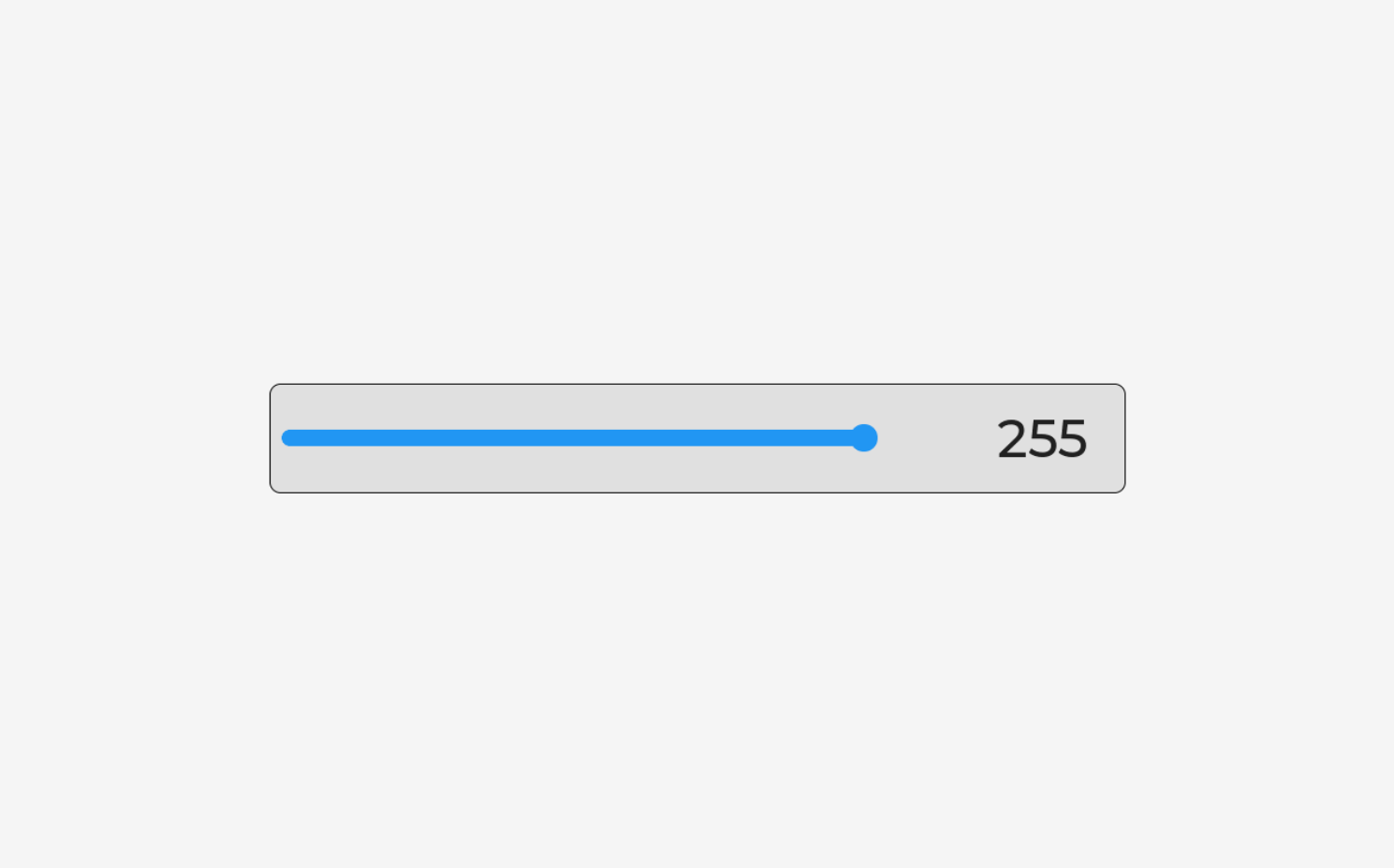
The Waveshare display utilizes an I2C-driven backlight controller at address 0x45. The brightness is managed via register 0x96:
#define BL_I2C_ADDR         0x45
#define BL_BRIGHTNESS_REG   0x96

static esp_err_t init_backlight(void)
{
    ESP_LOGI(TAG, "Initializing backlight (I2C addr=0x%02X)", BL_I2C_ADDR);

    i2c_device_config_t dev_cfg = {
        .dev_addr_length = I2C_ADDR_BIT_LEN_7,
        .device_address  = BL_I2C_ADDR,
        .scl_speed_hz    = 100000,
    };
    ESP_RETURN_ON_ERROR(i2c_master_bus_add_device(s_i2c_bus, &dev_cfg, &s_bl_dev),
                        TAG, "Failed to add backlight I2C device");

    uint8_t cmd1[] = {0x95, 0x11};
    ESP_RETURN_ON_ERROR(i2c_master_transmit(s_bl_dev, cmd1, sizeof(cmd1), 50),
                        TAG, "Backlight enable step 1 failed");
    uint8_t cmd2[] = {0x95, 0x17};
    ESP_RETURN_ON_ERROR(i2c_master_transmit(s_bl_dev, cmd2, sizeof(cmd2), 50),
                        TAG, "Backlight enable step 2 failed");
    uint8_t cmd3[] = {0x96, 0x00};
    ESP_RETURN_ON_ERROR(i2c_master_transmit(s_bl_dev, cmd3, sizeof(cmd3), 50),
                        TAG, "Backlight off failed");

    vTaskDelay(pdMS_TO_TICKS(100));

    display_set_brightness(10);

    vTaskDelay(pdMS_TO_TICKS(1000));

    ESP_LOGI(TAG, "Backlight initialized (full brightness)");
    return ESP_OK;
}
The brightness is controlled via a simple I2C transaction:
esp_err_t display_set_brightness(uint8_t val)
{
    uint8_t cmd[] = {BL_BRIGHTNESS_REG, val};
    return i2c_master_transmit(s_bl_dev, cmd, sizeof(cmd), 50);
}
The values range from 0 to 255, with the display only turning on the backlight starting from a value of 4 or higher.
MIPI-DSI Display Panel Initialization
This is the most complex part of the initialization. It consists of several sub-steps:
MIPI-DSI PHY Power Supply
The MIPI-DSI PHY (Physical Layer) requires a dedicated power supply of 2.5V. The ESP32-P4 features internal LDOs (Low-Dropout Regulators) that provide this voltage:
#define DSI_PHY_LDO_CHAN    3
#define DSI_PHY_LDO_MV     2500

esp_ldo_channel_handle_t phy_pwr = NULL;
esp_ldo_channel_config_t ldo_cfg = {
    .chan_id     = DSI_PHY_LDO_CHAN,
    .voltage_mv = DSI_PHY_LDO_MV,
};
ESP_RETURN_ON_ERROR(esp_ldo_acquire_channel(&ldo_cfg, &phy_pwr),
                    TAG, "Failed to acquire LDO channel");
DSI Bus Creation
The DSI bus is created using a 2-lane configuration. The Espressif component esp_lcd_jd9365 provides pre-defined macros:
esp_lcd_dsi_bus_config_t bus_cfg = JD9365_PANEL_BUS_DSI_2CH_CONFIG();
ESP_RETURN_ON_ERROR(esp_lcd_new_dsi_bus(&bus_cfg, &s_dsi_bus),
                    TAG, "Failed to create DSI bus");
The macro JD9365_PANEL_BUS_DSI_2CH_CONFIG() expands into a complete configuration structure with the typical parameters for 2-lane DSI (1500 Mbps per lane).
DBI Command Interface
MIPI-DSI panels support two modes:
- DPI (Display Pixel Interface): Continuous video stream for image rendering
- DBI (Display Bus Interface): Command mode for configuration registers
The DBI interface is required to send initialization commands to the JD9365 controller:
esp_lcd_panel_io_handle_t dbi_io = NULL;
esp_lcd_dbi_io_config_t dbi_cfg = JD9365_PANEL_IO_DBI_CONFIG();
ESP_RETURN_ON_ERROR(esp_lcd_new_panel_io_dbi(s_dsi_bus, &dbi_cfg, &dbi_io),
                    TAG, "Failed to create DBI panel IO");
JD9365 Panel with Waveshare-Specific Init Commands
The JD9365 is a generic display controller that can be used for various panels. Each panel requires a specific initialization sequence that configures parameters such as gamma curves, GIP (Gate-In-Panel) timing, power supply, and display timing.
This sequence is vendor-specific and is defined as an array of commands. I copied these values from the Waveshare code:
static const jd9365_lcd_init_cmd_t s_ws_init_cmds[] = {
    /* Page 0: Unlock password & DSI lane config */
    {0xE0, (uint8_t[]){0x00}, 1, 0},
    {0xE1, (uint8_t[]){0x93}, 1, 0},
    {0xE2, (uint8_t[]){0x65}, 1, 0},
    {0xE3, (uint8_t[]){0xF8}, 1, 0},
    {0x80, (uint8_t[]){0x01}, 1, 0},   /* DSI 2-lane mode */

    /* Page 1: Power and Gamma curves */
    {0xE0, (uint8_t[]){0x01}, 1, 0},
    // ... many other commands
};
The JD9365 uses a paged register model: register 0xE0 selects the active "page", after which all subsequent write accesses apply to the registers on that page. This is a common pattern used in display controllers to address more than 256 registers.
The complete panel configuration:
esp_lcd_dpi_panel_config_t dpi_cfg =
    JD9365_800_1280_PANEL_60HZ_DPI_CONFIG(LCD_COLOR_PIXEL_FORMAT_RGB565);
dpi_cfg.num_fbs = 2;  /* Double buffering */
dpi_cfg.video_timing.vsync_back_porch = 10;  /* Waveshare-specific */

jd9365_vendor_config_t vendor_cfg = {
    .init_cmds      = s_ws_init_cmds,
    .init_cmds_size = sizeof(s_ws_init_cmds) / sizeof(s_ws_init_cmds[0]),
    .mipi_config = {
        .dsi_bus    = s_dsi_bus,
        .dpi_config = &dpi_cfg,
        .lane_num   = 2,
    },
};

esp_lcd_panel_dev_config_t panel_cfg = {
    .reset_gpio_num = GPIO_NUM_NC,  /* No Reset-Pin */
    .rgb_ele_order  = LCD_RGB_ELEMENT_ORDER_RGB,
    .bits_per_pixel = 16,  /* RGB565 */
    .vendor_config  = &vendor_cfg,
};

ESP_RETURN_ON_ERROR(esp_lcd_new_panel_jd9365(dbi_io, &panel_cfg, &s_panel),
                    TAG, "Failed to create JD9365 panel");
It is important to set num_fbs = 2 for double buffering: The ESP32-P4 renders into one buffer while the other is being transmitted to the display. This prevents tearing effects.
Activating the Panel
After creating the panel handle, three final steps need to be performed:
ESP_RETURN_ON_ERROR(esp_lcd_panel_reset(s_panel), TAG, "Panel reset failed");
ESP_RETURN_ON_ERROR(esp_lcd_panel_init(s_panel), TAG, "Panel init failed");
ESP_RETURN_ON_ERROR(esp_lcd_panel_disp_on_off(s_panel, true),
                    TAG, "Panel display-on failed");
- esp_lcd_panel_reset(): Performs a software reset
- esp_lcd_panel_init(): Sends all init commands to the panel
- esp_lcd_panel_disp_on_off(true): Turns the display on (SLPOUT + DISPON commands)
Touch Controller Initialization
The GT911 touch controller communicates via I2C and is addressed using the generic esp_lcd_touch interface:
#define TOUCH_I2C_ADDR  ESP_LCD_TOUCH_IO_I2C_GT911_ADDRESS

esp_lcd_panel_io_handle_t tp_io = NULL;
esp_lcd_panel_io_i2c_config_t tp_io_cfg = {
    .dev_addr            = TOUCH_I2C_ADDR,
    .control_phase_bytes = 1,
    .dc_bit_offset       = 0,
    .lcd_cmd_bits        = 16,
    .flags = {
        .disable_control_phase = 1,
    },
    .scl_speed_hz = I2C_CLK_SPEED_HZ,
};
ESP_RETURN_ON_ERROR(esp_lcd_new_panel_io_i2c(s_i2c_bus, &tp_io_cfg, &tp_io),
                    TAG, "Failed to create touch I2C panel IO");

esp_lcd_touch_config_t touch_cfg = {
    .x_max        = PHYS_H_RES,  /* 800 */
    .y_max        = PHYS_V_RES,  /* 1280 */
    .rst_gpio_num = GPIO_NUM_NC,
    .int_gpio_num = GPIO_NUM_NC,
    .levels = {
        .reset     = 0,
        .interrupt = 0,
    },
    .flags = {
        .swap_xy  = 0,
        .mirror_x = 0,
        .mirror_y = 0,
    },
};

ESP_RETURN_ON_ERROR(
    esp_lcd_touch_new_i2c_gt911(tp_io, &touch_cfg, &s_touch),
    TAG, "Failed to create GT911 touch driver");
The touch configuration uses the physical resolution (800x1280 in portrait mode). The rotation will be handled later within LVGL.
LVGL Integration
The final step connects everything to LVGL. The esp_lvgl_port package takes care of the entire integration:
LVGL Port Initialization
const lvgl_port_cfg_t port_cfg = ESP_LVGL_PORT_INIT_CONFIG();
ESP_RETURN_ON_ERROR(lvgl_port_init(&port_cfg), TAG, "LVGL port init failed");
This creates the LVGL task, initializes the timers, and sets up thread safety (important for multi-core systems like the ESP32-P4).
Registering the Display
const lvgl_port_display_cfg_t disp_cfg = {
    .io_handle      = NULL,
    .panel_handle   = s_panel,
    .control_handle = NULL,
    .buffer_size    = PHYS_H_RES * 100,  /* 800 * 100 Pixel */
    .double_buffer  = true,
    .hres           = PHYS_H_RES,  /* 800 */
    .vres           = PHYS_V_RES,  /* 1280 */
    .monochrome     = false,
    .rotation = {
        .swap_xy  = false,
        .mirror_x = false,
        .mirror_y = false,
    },
    .flags = {
        .buff_dma    = false,
        .buff_spiram = true,  /* Buffer in PSRAM */
        .sw_rotate   = true,  /* Software-Rotation */
    },
};

const lvgl_port_display_dsi_cfg_t dsi_cfg = {
    .flags = {
        .avoid_tearing = false,  /* Must be false for sw_rotate */
    },
};

s_lvgl_display = lvgl_port_add_disp_dsi(&disp_cfg, &dsi_cfg);
Important Parameters:
- buffer_size = PHYS_H_RES * 100: The render buffer is 100 lines high. Larger buffers = faster, but consume more RAM.
- double_buffer = true: LVGL uses two buffers for fluid rendering.
- buff_spiram = true: Buffers reside in the PSRAM (32 MB), not in the limited SRAM.
- sw_rotate = true: Enables software rotation (see next section).
Landscape Mode via Software Rotation
The display is physically hardwired in portrait mode (800x1280), but landscape (1280x800) is better suited for many applications. I tried rotating the display using hardware commands, but that didn't work. It seems the display is genuinely locked into portrait mode. Therefore, I am using LVGL's software rotation:
lvgl_port_lock(0);
lv_disp_set_rotation(s_lvgl_display, LV_DISP_ROT_90);
lvgl_port_unlock();
Following this rotation, LVGL renders in 1280x800 and internally rotates the image before sending it to the display. This costs some performance but is significantly more flexible than hardware rotation. The avoid_tearing variable must be set to false when sw_rotate is active. Otherwise, conflicts will arise in buffer management.
Registering Touch Input
const lvgl_port_touch_cfg_t touch_cfg = {
    .disp   = s_lvgl_display,
    .handle = s_touch,
};
lv_indev_t *touch_indev = lvgl_port_add_touch(&touch_cfg);
The esp_lvgl_port package automatically handles the touch coordinate transformation to match the display rotation.
The Main Application
With all initialization steps completed, the actual GUI application can start:
extern "C" void app_main(void)
{
    ESP_LOGI(TAG, "============================================");
    ESP_LOGI(TAG, " ESP32-P4 + 10.1\" DSI Display Demo");
    ESP_LOGI(TAG, "============================================");

    /* Initialize display subsystem */
    ESP_ERROR_CHECK(display_init());

    /* Create GUI (from EEZ-Studio) */
    lvgl_port_lock(0);
    ui_init();  /* EEZ-generated code */
    lvgl_port_unlock();

    ESP_LOGI(TAG, "============================================");
    ESP_LOGI(TAG, " Initialization complete!");
    ESP_LOGI(TAG, "============================================");
}
The brightness can then be controlled at runtime via the slider:
void action_slider_set_backlight_brightness(lv_event_t * e) {
    lv_obj_t * slider = lv_event_get_target(e);
    int32_t value = lv_slider_get_value(slider);

    display_set_brightness(value);

    /* Update label */
    char str[10];
    sprintf(str, "%lu", value);
    lv_label_set_text(objects.label_brightness, str);
}
Summary
As you can see, initializing a MIPI-DSI display is significantly more complex than with parallel displays on the ESP32-S3. However, it follows a clear, modular structure:
- I2C bus for touch and backlight
- MIPI-DSI PHY power supply
- Create DSI bus with 2 lanes
- DBI command interface for panel configuration
- JD9365 panel with vendor-specific init commands
- GT911 touch via I²C
- LVGL integration with software rotation
When using the Waveshare components, the code is much shorter, but it was important to me to be able to follow and understand the individual steps. The code for this small demo is available on GitHub.
Pricing and Availability
The ESP32-P4-Module-DEV-KIT-C is available in various configurations, depending on whether you are looking for the standalone mainboard or the full bundle with the 10.1-inch display.
Directly from Waveshare:
If you don't mind international shipping, buying directly from Waveshare usually offers the best prices and access to all individual components:
- ESP32-P4-Module-DEV-KIT (Base Variant)
- ESP32-P4-Module-DEV-KIT-C (Full Kit with 10.1" Display)
- 10.1" DSI Touch Display (Standalone)
- RPi Camera (B) for the CSI Interface
Availability on Amazon:
For faster shipping and local support, the kit is also listed on Amazon. You will find three common options there (Affiliate-Links):
- The All-In-One Kit (Dev-Kit-C): The most convenient solution, as it includes all necessary cables and the 10.1" display.
- The Dev-Kit Only: Ideal if you already own a compatible DSI display or intend to use the board for other purposes, such as a high-performance controller with Ethernet.
- The 10.1" Display Only: Perfect for upgrading an existing setup.
Conclusion
At this point, I would first like to thank Waveshare for providing me with the ESP32-P4-Module-DEV-KIT-C for this review.
After spending several days working intensively with the board, my verdict is consistently positive. The DEV-KIT-C is a compact yet highly powerful board that enables many interesting projects.
The absolute highlight is the large 10.1-inch display. Thanks to the high-quality IPS panel, contrast, color reproduction, and viewing angle stability are absolutely outstanding. While the transition from classic ESP32-S3 boards with parallel RGB interfaces to MIPI-DSI involves a steeper learning curve and a significantly more complex initialization, the examples provided by Waveshare make this hurdle easy to overcome.
I couldn't find a single real weak point, except perhaps for the missing cable to flash the ESP32-C6, but that is complaining at a very high level. On the contrary: the fact that the C6 firmware can be updated independently via the SH1.0 connectors is a major plus. It makes the board future-proof for ESP-NOW applications once Espressif finally integrates this feature into the ESP-Hosted-MCU firmware.
I think I have finally found the display for the next generation of my weather station.