CrowPanel Advance 7.0 Update: Changes in Versions 1.2 and 1.3
In my original article about the CrowPanel Advance 7.0 display, I criticized that the backlight was not controllable via PWM. This made the display unsuitable for my weather station, even though I find the concept with the expandable modules very interesting. Elecrow responded to the feedback, and with hardware revisions 1.2 and 1.3, this problem has been solved. In this update article, I will show you what exactly has changed and whether the display is now suitable for my weather station
The Design of the new CrowPanel Advance Displays
The hardware is fundamentally identical for both displays. The central component is again an ESP32-S3 in the form of an ESP32-S3-WROOM-1-N16R8 module and a 7-inch IPS display. The microcontroller has 512KB of SRAM, 8MB of PSRAM, and 16MB of Flash memory available. In these models as well, three of the 36 GPIO pins are used for the Octal SPI PSRAM. The following diagram illustrates how the remaining 33 GPIO pins are connected to the rest of the display's components.
If you compare this diagram with version 1.0 of the display, you won't notice much difference at first glance. In fact, Elecrow basically only changed one component: the I/O expander. In the old display, some signals were controlled by a PCA9557 8-bit I/O expander. This component controls 8 inputs/outputs and is managed via the I2C bus. In the new displays, this is now handled by an STC8H1K28 microcontroller. This is an 8051-compatible microcontroller, which is also controlled via the I2C bus and runs in slave mode. This has made the control significantly more flexible. The display brightness, for example, is now controlled using the PWM periphery of the STC8H1K28.
A look at the board, in this case version 1.2, also shows that the old and new displays are nearly identical.
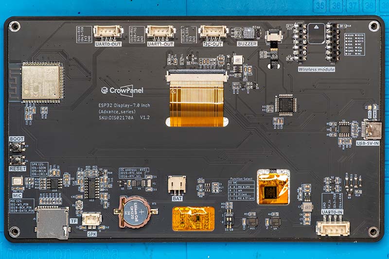
There are even fewer differences between version 1.2 and 1.3 of the display. The hardware of the two displays is essentially identical. They only differ in the firmware of the STC8H1K28. Version 1.2 can only control the brightness in 6 steps, whereas version 1.3 now offers 246 steps. Since it is not possible to change this firmware using standard methods, Elecrow likely had to produce a new version of the display.
Demo Application with ESP-IDF and LVGL
To try out the new brightness control, I wrote a small application that allows you to set the clock and adjust the brightness.
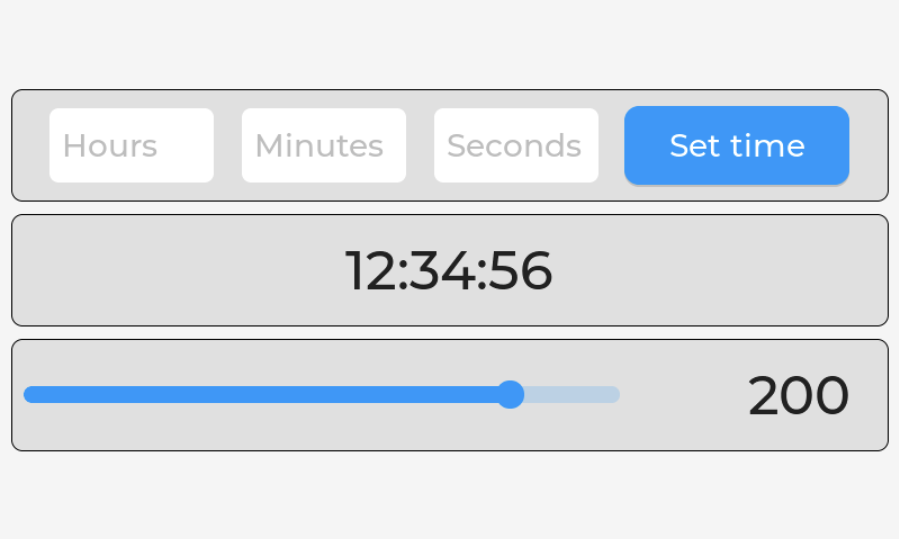
In the application, the following aspects of an ESP32 project are covered:
- Creating layouts with EEZ-Studio. Since I disagree with SquareLine Studio’s pricing model and EEZ-Studio is a fully-featured open-source alternative, I will be using this application exclusively from now on.
- Control of the display and touch controller using ESP-IDF and the LVGL framework.
- Handling events in the user interface and updating the display accordingly.
- Updating the display from within a task.
- Control of the RTC (real-time clock).
- Control of brightness and the buzzer via the IO expander.
To control the brightness or turn on the buzzer, I wrote a driver to control the STC8H1K28. The code for this is very manageable and only sends specific values to the I2C device, which has the address 0x30:
#include "stc8h1k28.h"
#include "driver/gpio.h"
#include "esp_log.h"
#include "esp_check.h"
#include <string.h>
#include "freertos/FreeRTOS.h"
#include "freertos/task.h"

static const char *TAG = "STC8H1K28";


esp_err_t stc8h1k28_init(i2c_master_bus_handle_t bus_handle, stc8h1k28_handle_t *extender_handle, const i2c_device_config_t *config) {
    ESP_RETURN_ON_FALSE(bus_handle && extender_handle && config, ESP_ERR_INVALID_ARG, TAG, "Invalid arguments");

    stc8h1k28_dev_t *dev = calloc(1, sizeof(stc8h1k28_dev_t));
    ESP_RETURN_ON_FALSE(dev, ESP_ERR_NO_MEM, TAG, "Memory allocation failed");

    // Initialize I2C device
    ESP_RETURN_ON_ERROR(
        i2c_master_bus_add_device(bus_handle, config, &dev->i2c_dev),
        TAG, "Failed to add I2C device");

    *extender_handle = dev;
    ESP_LOGI(TAG, "stc8h1k28 initialized successfully");
    return ESP_OK;
}

void stc8h1k28_deinit(stc8h1k28_handle_t dev) {
    if (dev) {
        if (dev->i2c_dev) {
            i2c_master_bus_rm_device(dev->i2c_dev);
        }
        free(dev);
    }
}

esp_err_t stc8h1k28_set_brightness(stc8h1k28_handle_t dev, uint8_t brightness) {

    ESP_RETURN_ON_ERROR(
        i2c_master_transmit(dev->i2c_dev, &brightness, 1, -1),
        TAG, "Failed to set time");
    return ESP_OK;
}

esp_err_t stc8h1k28_buzzer_on(stc8h1k28_handle_t dev) {

    uint8_t value = 246;
    ESP_RETURN_ON_ERROR(
        i2c_master_transmit(dev->i2c_dev, &value, 1, -1),
        TAG, "Failed to set time");
    return ESP_OK;
}

esp_err_t stc8h1k28_buzzer_off(stc8h1k28_handle_t dev) {

    uint8_t value = 247;
    ESP_RETURN_ON_ERROR(
        i2c_master_transmit(dev->i2c_dev, &value, 1, -1),
        TAG, "Failed to set time");
    return ESP_OK;
}
Elecrow provides a lot of information about the displays on their Wiki page and on GitHub. My code for version 1.3 of the display is also available on GitHub.
With this, the latest version of the display is well-suited for the weather station, as the control of the backlight was the only point of criticism for version 1.0 (and also 1.2). I am currently migrating the weather station's layout from SquareLine Studio to EEZ-Studio, and as soon as that is finished, I will adapt the code for the Elecrow display.